A microphone cable can cross a stage full of electrical activity and still deliver a very small signal that someone wants to hear. Its job is not only to carry sound information. It must help the receiver distinguish that information from electrical trouble acquired on the journey.
Balanced audio uses two signal conductors and a receiver that responds to their difference. Interference that appears equally on both conductors can then largely disappear from the subtraction. The useful trick is not to keep every disturbance out. It is to make a disturbance arrive in a form the receiver can reject.
Make the arithmetic visible
Begin with a deliberately idealized pair of signal voltages: +0.2 and −0.2 in arbitrary units. Their difference is 0.4. Add the same unwanted 0.1 to each. The receiver now sees +0.3 and −0.1, but their difference is still 0.4. The shared addition has not become part of the differential result.
Texas Instruments' design article explains this common-mode rejection and the line receiver's role. Common mode means that the disturbance is shared by the two lines. Differential mode means that the two lines differ. Those descriptions concern relationships between signals, not whether a noise sounds like a hum or a hiss.
Add common noise, then unbalance it
A silent numerical subtraction model with explicit arbitrary units and mismatch.
In the model, increase the common interference while keeping the two line disturbances matched. The recovered result remains the same. Then introduce a mismatch. Part of the disturbance survives because subtraction cannot remove a difference that is genuinely present between the two inputs.
The word “balanced” hides a frequent misunderstanding
It is tempting to define a balanced output as two equal-and-opposite copies of the wanted waveform. That arrangement is common and useful, but it is not the defining condition. The impedances of the two signal paths matter for rejection of interference. Impedance describes how a path responds electrically; a cable cannot be judged by waveform symmetry alone.
A balanced system includes source, connection, and receiver. Noise rejection must remain meaningful even when no wanted signal is playing. An attractive pair of opposite waveforms is therefore not sufficient evidence that the whole interconnection is well balanced. Rane’s interconnection reference shows why the equipment and grounding arrangement belong to the system-level explanation.
A silent test of the definition
Imagine switching off the wanted tone while leaving an interconnection in a noisy electrical environment. The desired result is still a small unwanted output. If your explanation of balance depends entirely on an inverted copy of the wanted music, it has lost the case where the music is absent. The impedance relationship has not disappeared merely because the signal has.
The receiver has limits too
An ideal subtraction is easy to write down. Real components have tolerances, and their responses vary with frequency. Source impedances and the receiver's input impedances affect how interference is converted into a differential error. A small mismatch can matter when the unwanted common signal is much larger than the desired difference.
Rane’s specification guide explains why common-mode rejection figures need stated conditions, including frequency and the impedances of the test source. A carefully matched laboratory result does not automatically describe every studio connection. The test conditions belong with the number.
Our calculator makes that principle visible without attempting to design an input stage. If the common disturbance is 1 and one side receives 0.98 while the other receives 1.00, a residual difference of 0.02 remains. If the disturbance is much smaller, the same percentage mismatch leaves a smaller error. Relative balance and absolute disturbance both matter.
A connector is a clue, not a guarantee
A three-contact connector may be used for a balanced connection, stereo audio, or another purpose, depending on the equipment. Its shape alone does not tell the complete story. A useful reading habit is to check the device's documented input and output arrangements rather than infer everything from the number of contacts.
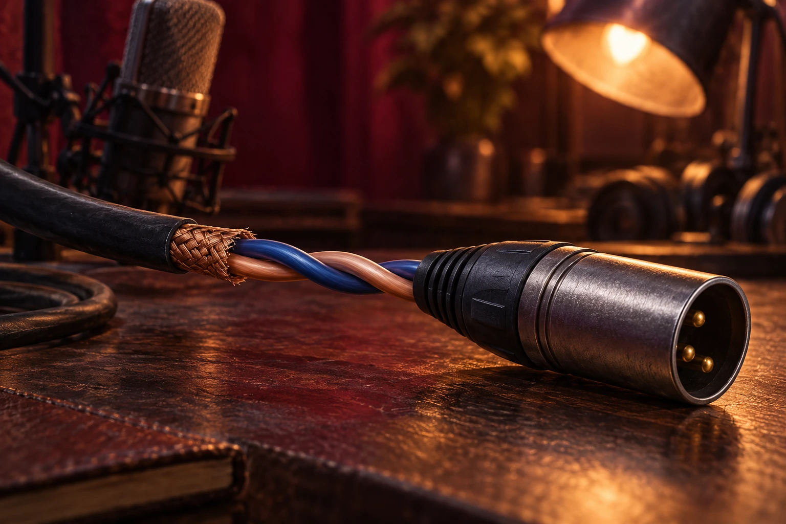
The illustration opens up a cable to show two distinct conductors, but it is not a wiring instruction. Shielding, grounding, and signal conductors have different jobs. The explanatory subtraction should not be turned into an improvised instruction to remove protective connections or alter powered equipment.
Balanced audio is an elegant example of designing around a relationship. The two wires do not need private, perfectly quiet journeys. They need a sufficiently similar encounter with the unwanted world, followed by a receiver that can use their difference well.
Follow the evidence: Texas Instruments: balanced audio inputs; Rane: sound system interconnection; Rane: audio specifications.
Explore all 80 new articles · Browse the complete illustrated collection
Explore more art, ideas, experiments, and independent projects at Incoprea.