Showing posts with label Materials. Show all posts

Sunday, October 25, 2026

Niello: The Dark Material That Makes Silver Draw in Black

A line cut into polished silver can be surprisingly hard to see. Turn the object and the groove flashes; turn it again and the reflected room competes with the design. Fill the cut with a dark material and the line behaves differently. Niello exploits that difference, allowing a metal surface to carry a pattern with the clarity of black drawing.

Imagined silver panel with raised-looking vines on a black ground beside an engraved design.
Conceptual study of bright silver ornament against a dark ground.

The cut and the filling are different things

The Museum of Fine Arts, Boston’s CAMEO materials database defines niello decoration through an engraved pattern filled with black inlay. Engraving creates a recess. Niello supplies a material within it. The distinction is simple, but it prevents a frequent confusion: an engraved object is not necessarily nielloed, and a dark mark on metal is not enough to establish the presence of niello.

The resulting design depends on contrast. A bright ground can catch the light while the filled pattern remains dark. A narrow border, a curl of foliage or a short inscription can become easier to distinguish. The maker is working with the behaviour of a surface as much as with the outline of a motif.

Niello is not simply black paint. Conservation research identifies it as a material composed of one or more metal sulphides. In their technical note, Richard Newman, James R. Dennis and Ellen Farrell discuss silver, copper and lead sulphides and the different properties that combinations can have. “Niello” names a family of related materials, rather than one unchanging substance used everywhere.

Why appearance is not a chemical identification

The same conservation paper warns that dark patinas, resinous materials, lacquers and enamel can be confused with niello. This is a useful limit on what we can learn from a photograph. We may be able to describe a dark pattern very carefully while remaining unable to identify its composition. A museum’s material record and scientific examination can answer questions that visual confidence cannot.

Susan La Niece’s survey of 180 objects demonstrates why the distinction matters historically. Her analysis found important changes in the sulphides used across objects of different dates and regions. Roman examples generally used a single metal sulphide; later materials could combine more than one metal. A modern shorthand recipe would conceal that variation rather than explain it.

The survey also relates composition to working properties. Different materials do not behave identically when incorporated into a design. That means material analysis can contribute to an account of technique, even when an object’s overall appearance is familiar. Two black lines can look much alike while carrying different evidence about the practices that produced them.

Similar effects, different materials

Enamel is another way to put a contrasting substance onto metal, but it is not the same material. The Met’s study of Islamic jewellery defines enamel as decoratively applied, heat-fused glass. It can occupy a recess and create a strong colour contrast, so the visual resemblance to niello can be understandable. The material distinction remains essential.

Ordinary tarnish introduces a third possibility. A darkened silver surface may contain silver sulphide, but that does not mean it was deliberately laid into an engraved design as niello. Chemistry alone does not explain intention or technique. The placement of the material, the object’s construction and the evidence of workmanship must also be considered.

This is why “black decoration” is sometimes the most honest first description. It records something visible while leaving the more demanding identification open. Careful looking begins with such observations. It does not become less interesting because the answer requires an instrument or a conservator’s report.

At one scale, the pattern tells a story or marks a border. At another, it reveals decisions about the width and spacing of lines. A design that is too dense can merge into a dark mass; one that is very fine can disappear into reflected light. The maker has to judge both the image and the surface that will carry it.

Look at a spoon instead of a treasure

The Philadelphia Museum of Art’s Child’s Spoon, dated 1890–1900, offers a useful small example. Its label explains that engraved lines were filled with a dark material and the surface was burnished. The museum also notes that niello work is unusual on American silver. A familiar object therefore opens onto a technique that may be easier to notice on ceremonial metalwork.

Look first at the boundary between the dark pattern and the bright metal. Does the line have the regularity of a repeated border, or does it widen to form an image? Then look for light reflected from the surrounding surface. The decoration has to remain legible while the ground changes with the viewing angle. Even a modest utensil can make that problem visible.

Three terms that describe different parts of the work
TermWhat it identifies
EngravingRemoving material to make a cut.
Niello decorationA dark metal-sulphide material within the design.
EnamelHeat-fused glass supplying a contrasting material.

If the collection image will not enlarge, read the spoon’s object label and compare it with the CAMEO’s definition. You can still separate a technique for making recesses from a material used to fill them. This is a more reliable starting point than judging every dark patch by colour alone.

Niello makes an unusually clear connection between drawing and metalwork. The design can be read as a line, but its persistence depends on a physical arrangement of substances. Once that arrangement becomes visible to you, the dark parts stop looking like empty gaps. They become active components of the object’s surface.

Explore more art, ideas and independent projects at Incoprea.

Two Metals Disagree, and a Thermostat Moves

A traditional mechanical thermostat can detect temperature without a digital sensor or a battery-powered display. Its sensing element may be a strip made from two permanently joined metals. When the room warms, the pair bends. Rolled into a coil, that small change becomes a useful rotation. The motion begins with a disagreement that the bonded layers cannot resolve by separating.

Illustration of a spiral temperature element above a close view of a curved two-layer metal strip.
A coil and a curved bonded strip make differential expansion easier to see.

Two lengths trapped together

Most familiar metals expand when warmed over ordinary operating ranges, but they do not all expand by the same amount. If two loose strips are heated, each can take its preferred new length. Bond them along their length and they must remain connected. A straight arrangement can no longer accommodate both preferred changes without internal stress. Curving allows the layer that expands more to follow the longer outside path.

The lower-expansion layer lies toward the inside of the bend on heating from the reference condition. Cooling reverses the change in curvature. The National Bureau of Standards' Thermal Expansion of Solids describes this bimetallic flexure and its conversion into angular or linear motion. The important word is “different.” One layer does not need to shrink when warmed. Two positive expansion coefficients can produce the effect.

How small can the mismatch be?

For a modest temperature interval, a free strip's length change can be approximated as its initial length times its expansion coefficient times the temperature change. As a deliberately illustrative example, take two 100-millimeter strips with coefficients of 20 and 10 millionths per degree Celsius. Warm them by 20 degrees. Their free expansions would be 0.040 and 0.020 millimeter. The difference is only 0.020 millimeter.

These are chosen round numbers, not measurements of a particular thermostat alloy. They explain why a small mismatch is available, but they do not predict the final bend. Curvature also depends on layer thickness, stiffness, bonding, and geometry. A numerical coefficient difference alone is not enough to calculate a device's pointer movement. The bonded strip turns that constrained mismatch into a displacement that can be easier to use than the tiny free length difference.

Why wind the strip into a coil?

A long straight strip would need space. A spiral or helix fits useful length into a compact region and can turn a shaft or contact mechanism. Fix one end and allow the other end to respond. Changes in curvature add up along the element, producing a rotation. The device can then move a pointer across a scale or change the state of an electrical contact through a suitable mechanism.

WIKA's technical description of mechanical thermometers identifies both helical and spiral bimetal elements. In a dial thermometer, temperature changes rotate the attached spindle and pointer. The sensing element is inside a stem that must exchange heat with the measured material. The dial is a readable output; the actual sensing process is a change of shape. A decorative circle on the front does not itself know the temperature.

This distinction also explains a delay. The element responds to its own temperature, which must approach that of its surroundings through heat transfer. A protective stem, installation depth, airflow, and contact with the measured material affect that process. A pointer that has started to move is not necessarily at its settled reading. Mechanical simplicity does not remove response time or calibration requirements.

Measuring is different from switching

A thermometer aims to display a value. A thermostat aims to control something around a chosen operating condition. In one arrangement, the temperature-sensitive movement operates contacts. Changing the setting adjusts the relationship between the element's motion and the switching point. The thermostat then interacts with a larger system: a heater or cooler changes the surroundings, and the changed temperature eventually acts on the sensing element again.

NASA's educational material on thermometers and thermostats connects thermal expansion with that control loop. The sensing strip does not supply the energy to heat a room. It supplies a movement that can govern a much larger energy flow. That difference between sensing and power is easy to overlook when a small dial appears to command a large appliance.

A controlled gap between opening and closing

Many switching controls deliberately use different temperatures for opening and closing. The gap is often called the differential. Without a suitable separation or snap mechanism, a contact near its threshold could switch repeatedly as tiny temperature changes and disturbances occur. A well-chosen differential allows the system to cycle within an intended band. It also means the setpoint should not be imagined as an infinitely sharp temperature that the whole room holds at every instant.

The Therm-O-Disc bimetal control catalog explicitly defines differential as the difference between nominal open and close temperatures. Some controls use a bimetal disc that snaps between shapes, rather than a slowly turning coil. That is another way to turn differential expansion into a decisive action. Product-specific ratings and calibration tolerances belong to the individual control, not to all bimetal devices.

Observe a finished instrument

A kitchen dial thermometer, used within its instructions, offers a safe observation. Compare its settled reading in room-temperature water with its later reading in comfortably warm water. Keep the sensing region immersed as the maker specifies, and allow time for stabilization. The observation shows a complete instrument responding, not the alloy's raw coefficient. There is no need to open a thermostat, disturb electrical contacts, or handle an old mercury switch.

The familiar dial conceals a useful translation. A temperature difference becomes unequal preferred lengths. A permanent bond makes those lengths negotiate through curvature. Geometry turns the bend into a pointer movement or a switching action. The device works because its two materials remain joined while responding differently to the same surroundings.

Sources and further reading

Continue exploring: The Solid That Can Shrink When You Warm It; The Drinking Bird Is a Heat Engine With a Thirst.

Explore more at Incoprea.

The Reflector That Sends Light Back Toward Its Source

A roadside sign can look quietly ordinary during the day and suddenly blaze under headlights. It has not necessarily switched on a lamp. Its surface is sending a useful share of incoming light back toward the place it came from. A bicycle reflector performs the same broad trick. The effect is called retroreflection, and it differs from both a mirror's glare and white paper's scattered glow.

A bicycle reflector and roadside sign, with conceptual insets of prismatic and glass-bead structures.
Reflective signs and bicycle fittings use tiny structures to return light toward its source.

Three different destinations for the light

A flat mirror reflects light in a direction set by its orientation: the angle of reflection matches the angle of incidence. Tilt the mirror and its bright reflection moves. A matte surface sends light into many directions, allowing observers at different positions to see it. A retroreflector concentrates returned light near the incoming direction over a useful range of orientations. That makes it especially effective when the observer is close to the light source.

The Federal Highway Administration explains that sign sheeting commonly uses tiny glass beads or cube-corner structures. Both send light back toward its source, though their performance differs. “Reflective” is therefore a broad everyday word. Knowing that a surface reflects light does not yet tell us where the reflected light goes.

A corner performs three reversals

Consider three reflecting surfaces meeting like the inside corner of a cube. Each reflection reverses one component of the light's travel direction. After encounters with the three mutually perpendicular faces, all three components have reversed. The outgoing ray travels back along a direction nearly opposite the incoming one. The FHWA roadway delineation handbook describes this component-by-component reversal for cube-corner markers.

Real optical corner cubes may be solid prisms using total internal reflection, rather than three separate little metallic mirrors. Their entrance openings, material, face angles, and surrounding medium affect which rays can complete the required route. A corner cube is not equally effective from every imaginable orientation. If light cannot enter the proper faces or follow the intended reflections, the convenient geometric description no longer delivers the promised return.

Glass-bead systems achieve a similar destination by a different path. A bead acts as a tiny lens. It bends light toward a reflective region behind it, and the returning light is bent again as it leaves. The detailed result depends on the bead's optical properties, its embedding, and the reflective backing or surrounding marking material. A Texas Transportation Institute report explains the spherical-lens and prismatic approaches. A handful of ordinary glass marbles is not automatically equivalent to engineered sign sheeting.

Why the driver's eyes matter

The returned light forms a distribution around the source direction, not an infinitely thin line. A driver's eyes are separated from the headlights. The angle between the incoming headlight direction and the direction to the observer is called the observation angle. A surface that sent every photon exactly into the lamp might be less useful to the driver. Practical materials must provide suitable return toward the nearby eyes as well.

The FHWA workshop account of viewing geometry distinguishes the entrance angle. It describes how the incoming illumination meets the reflector relative to the surface's reference axis. Turn the sign or move the car and both the illumination and viewing geometry can change. Consequently, “how bright is this reflector?” is incomplete without conditions. A material measured under one geometry need not produce the same value under another. Nor does a high return coefficient guarantee readability through fog, dirt, or a poor windshield.

A useful thought experiment is to imagine two people looking at the same bicycle reflector. One holds a flashlight beside their face. The other stands well to the side. The first person may see a much brighter return because their eyes are near the source. They are not necessarily looking at different paint or experiencing a change in the reflector. Their positions select different parts of its returning light pattern.

The same family of geometry reaches the Moon

Retroreflectors also give surveyors and spacecraft a target with a known location. NASA Goddard's miniature lunar arrays use eight corner-cube prisms arranged on a small dome. NASA lists an acceptance angle of 17 degrees for each prism. The domed arrangement allows multiple directions of useful access. That specified angle is a property of those prisms, not a universal limit for all retroreflectors.

Timing a returned light pulse can support a distance measurement. The reflector itself does not need to broadcast a radio reply or generate its own flash. It supplies a passive optical destination. However, the ranging system still needs an appropriate source, receiver, pointing, timing, and treatment of the measurement uncertainties. A simple optical principle sits inside a demanding experiment. The familiar nighttime reflector and the lunar target share a geometric strategy, not identical performance.

A tabletop comparison

In a dim room, place a clean bicycle reflector beside white paper. Use an ordinary flashlight from a comfortable distance, first near your eye level and then farther to the side while you keep looking from the original position. Keep the beam away from faces and do not use a laser. Notice which surface changes brightness most strongly. The comparison is qualitative; it does not certify a safety product or measure its road performance. It does reveal that the destination of reflected light can matter as much as the amount of light a surface receives.

Sources and further reading

Continue exploring: Gold Leaf: How a Small Piece of Metal Becomes a Field of Light; Why a Camera Can Turn One Small Light Into a Star.

Explore more at Incoprea.

A Braided Air Muscle Gets Shorter by Getting Wider

A balloon tends to get larger when air enters it. A braided pneumatic artificial muscle can do something less obvious: it gets wider and shorter at the same time. The air does not pull its ends together directly. A carefully constrained sleeve changes what inflation is allowed to do. The apparent contradiction disappears when the fibers become the main characters.

A braided pneumatic actuator shown long and narrow above, shorter and wider below.
Two illustrated states show how a braided pneumatic actuator gets wider as it shortens.

The braid decides which way the energy goes

A common McKibben-type actuator has an elastic inner tube inside a woven sleeve. The fibers cross diagonally around the tube. When pressure makes the inner tube expand radially, the braid opens to a larger diameter. If its strands cannot appreciably stretch, their geometry requires a shorter distance between the ends. End fittings transmit the resulting axial tension to a load. Pressure provides the energy; the braid gives that energy a useful direction.

This is a geometric constraint, rather than the rubber somehow deciding to imitate a living muscle. In an ideal model, the length of a helical strand remains fixed while its angle to the actuator's axis changes. As the strand lies more around the circumference, less of it extends along the axis. The structure-based study by Al-Ibadi and colleagues relates changing length, diameter, and braid angle to the actuator's behavior. The actual device adds elastic material, contact, and end effects to that simple picture.

Pulling hard is different from pulling far

One tempting mistake is to imagine constant force throughout the stroke. Many braided muscles provide their largest available pulling force near the start of contraction, then less as they shorten. Pressure, current length, initial geometry, and external load all matter. A muscle prevented from shortening can develop tension without completing a stroke. A freely shortening muscle reaches a different condition because little external force resists it.

Commercial constructions are not all identical to a loose laboratory sleeve. Festo's DMSP documentation describes reinforced contractible tubing with aramid fibers and specifies its own operating ranges. Some listed sizes permit up to 25 percent contraction, while the smallest listed size has a different limit. Those are product limits for defined devices. They should not be repackaged as a guarantee that every artificial muscle shortens by one quarter.

A percentage can still make the motion easier to picture. For an illustrative 200-millimeter active length, a 20 percent contraction would mean a 40-millimeter reduction, leaving 160 millimeters. That arithmetic says nothing about the force available at the end, the pressure required, or whether a particular actuator allows it. Stroke and load capacity must be read together. A dramatic unloaded demonstration can hide how differently the same device behaves while doing work.

The useful imperfection of softness

A piston cylinder usually suggests a sliding rigid rod and a closely guided path. A pneumatic muscle is a tensile element. It normally needs an external load, spring, or opposing actuator to lengthen it again. Two muscles can oppose one another around a joint, with their forces controlling position and resistance to motion. Compliance can be useful when a mechanism must interact with changing loads. It also makes accurate positioning a control problem.

A 2014 experimental control study examined different braided prototypes and closed-loop regulation of contraction. The need for feedback follows from the device's changing force and length relationship. Giving a pressure command is not the same as specifying a unique position under every load. A controller may need to measure movement and adjust the air supply as conditions change.

Friction between strands and between the sleeve and bladder contributes to hysteresis. The path during contraction may differ from the path during relaxation. Elastic material adds its own resistance and time dependence. These effects mean that a compact ideal formula cannot describe every real cycle exactly. An actuator can be mechanically simple while remaining mathematically inconvenient. Simplicity of parts does not imply simplicity of behavior.

A braid can also become a sensor

In Contraction Sensing with Smart Braid McKibben Muscles, researchers made the sleeve from conductive insulated wires. Its changing geometry changed an electrical property that could be used to estimate contraction. The same structure that constrained the motion also provided information about it. That is a different claim from saying a conventional textile braid already contains a complete position sensor. The sensing function depended on the study's materials and measurement arrangement.

The idea is especially appealing because it reduces the separation between a machine's body and its measurement system. Instead of adding a rigid ruler beside a soft actuator, engineers can ask what the changing body itself reveals. The paper's results remain tied to the tested design and calibration. Stretch, manufacturing differences, and the surrounding system still deserve attention before such sensing is treated as interchangeable across devices.

Try the geometry without compressed air

A woven finger-trap toy offers a safe analogy. Gently shorten an empty one between your hands and notice its diameter increase. Then lengthen it and watch it narrow. The analogy demonstrates the braid relationship, not the pressure vessel, force output, or control system. No inflation is needed. The key observation is that a material can become a mechanism when its allowed motions are constrained. Here, a diagonal network turns getting bigger in one direction into getting smaller in another.

Sources and further reading

Continue exploring: Why a Bicycle Wheel Carries Weight by Losing Some Tension; The Gearbox That Lets Two Wheels Disagree.

Explore more at Incoprea.

Gold Leaf: How a Small Piece of Metal Becomes a Field of Light

A sheet of gold leaf looks almost too slight to count as metal. A loose edge can wrinkle like tissue, yet the surface it covers may read as a solid expanse of gold. The contradiction is part of the craft: very little material can exert a large visual presence.

Follow that leaf backward from an illuminated page or gilded frame. Before it was placed, it was beaten. Before beating, the metal had to be prepared and divided. Its brilliance on the finished object depends on another set of decisions about the surface beneath it and the light that reaches it.

A thin wrinkled gold leaf rests on a cushion beside a closed beating packet and a resting hammer.
A reconstructed craft still life: leaf, cushion, beating packet and hammer.

Spreading metal without turning it into paint

Gold is exceptionally malleable: it can be hammered into thin sheets. The Royal Society of Chemistry's material account distinguishes its softness and the thin leaf used in decoration. Malleability describes the ability to change shape under compression; it does not mean that a finished leaf is sturdy enough to handle like a coin.

There is a simple geometric relationship behind the spectacle. Spread the same amount of material over a larger area and its average thickness decreases. The goldbeater's problem is to make that spreading controlled and sufficiently even, rather than ending with tears and isolated thick spots.

Nor is thinness a single universal specification. A museum label might describe sheet, foil or leaf, and the terminology and thickness need context. The Metropolitan Museum's account of ancient Egyptian gold discusses both very thin leaf and thicker foils or sheets. A numerical thickness reported for one tradition should not be assigned to every gilded object.

The hammer meets a packet

Traditional beating is less like striking an exposed square of kitchen foil than the usual workshop image suggests. Getty's Gilding Notes: The Traditional English Method describes gold placed between separating sheets and secured as a packet. Historical interleaves included prepared animal membranes; later materials also served the process.

The packet lets a worker beat many small pieces while keeping adjacent gold surfaces separated. As the pieces expand, they are removed, divided and interleaved again for further beating. Repeated spreading and subdivision produce numerous thin leaves from the prepared metal. The details of packets, tools and sequences belong to particular craft practices, rather than a recipe shared unchanged by every goldbeater.

Notice what the reconstructed still life shows: the delicate loose leaf and the closed beating packet occupy different stages of the work. The hammer is not about to strike the unsupported finished leaf. That distinction helps connect the apparent force of the making with the fragility of the result.

The craft also involves sustained judgment. A German national intangible-heritage entry on Schwabach goldbeating describes precise hammering developed through practice. The surviving tradition is useful evidence that making leaf is skilled work, even when the finished gold seems almost weightless.

A gold surface may be a layered object

The Met gives a concrete ancient example: Hapiankhtifi's wooden model broad collar carries gold leaf over gesso and linen. A golden appearance therefore need not mean a solid gold body. The supporting object, prepared ground and metal surface each contribute something different.

For manuscript illumination, the Fitzwilliam Museum distinguishes leaf from shell gold. Leaf is metal beaten thin and laid down; shell gold is powdered metal mixed with a binder and applied like paint. Both contain gold, but they arrive on the page through different working methods.

The museum also describes prepared grounds and burnishing, as well as patterns incised or punched into gilded areas. Such treatment can shape the way a surface catches light. It is misleading to explain a brilliant illuminated initial through the precious metal alone while ignoring the structure that gives the thin layer its shape.

Watch the placement, then watch the light

The V&A's conservation film about the Salisbury Cross offers a useful view of applying leaf. Begin with the hands and tools. Look for the difference between moving a leaf and pressing or finishing it once it has reached the prepared surface. The activity is to observe the conservators' method, rather than to treat a historic object as a home practice surface.

V&A conservators demonstrate work on the Salisbury Cross. Watch the film directly.

For a simple comparison at home, use clean aluminium foil, not gold leaf. Leave one section reasonably smooth and gently wrinkle another. Hold both in the same room light and change the viewing angle. The small folds send bright reflections in different directions. This models a basic surface effect; it does not reproduce gold's color or the craft of burnishing.

Return to a museum image of gilding and look for edges, worn places or patterned areas. Ask which visible forms belong to the gold itself and which arise from its support. A photograph captures one lighting arrangement, so a quiet patch on screen may become brilliant when a real object or viewer moves.

Gold leaf joins the scale of a small packet on a workbench to the scale of a glowing wall or page. Hammering makes the metal spread; preparation gives it a home; light makes its thin surface visible. The broad field of gold is the result of those relationships, not simply the quantity of precious metal beneath your eye.

Read more: Royal Society of Chemistry: Gold · Getty: Gilding Notes · The Met: Gold in Ancient Egypt · German UNESCO Commission: Schwabach goldbeating · Fitzwilliam Museum: Painting with metals · V&A: Metalworking techniques

Egyptian Faience: A Bright Blue Surface Built Around Crushed Quartz

Look at a small turquoise Egyptian bead and imagine its color continuing all the way through. That assumption can be wrong. Beneath the bright surface of Egyptian faience lies a body made largely from quartz particles. A glossy outside and a pale granular interior belong to the same carefully manufactured object.

The material turns an everyday visual shortcut into an archaeological puzzle. We often identify things by their surfaces. Faience asks us to consider how a surface was produced, what supports it and which parts of its manufacture remain hidden after thousands of years.

Turquoise glazed beads sit beside a broken sample whose pale granular interior contrasts with its thin bright surface.
An illustrative material study contrasts the glazed surface with a pale quartz-rich core.

A ceramic with a quartz-rich body

Egyptian faience is a glazed siliceous ceramic, rather than ordinary clay pottery with a blue coating. The Australian Museum's material account describes ground quartz or sand combined with smaller amounts of other constituents. The Metropolitan Museum's technical essay identifies alkaline salts, lime and colorants as important parts of the technology. Copper produces the characteristic turquoise blue, although faience could have other colors.

The distinction from glass is about structure as well as ingredients. A faience object retains a particulate quartz-rich body beneath its glaze. Calling it simply blue glass loses that relationship. Calling it pottery can suggest a clay body that is not the defining material here. Museum terminology is useful because it directs attention toward the object's construction.

There is another naming trap. The word faience is also used for European tin-glazed earthenware associated with places such as Faenza. Egyptian faience is a different material tradition. A shared modern label does not establish an identical recipe or a historical journey between the two.

Three routes toward a glazed surface

The Met describes three important glazing approaches. They can be used separately or in combination, so an object need not fit a perfectly isolated category. The common result is a glazed surface; the route by which its ingredients arrive there can differ.

Different manufacturing routes can produce a bright surface.
ApproachWhat changes
Direct applicationA glaze mixture is placed on the formed body, for example by brushing or dipping.
EfflorescenceSoluble components in the body migrate toward the surface during drying, helping supply the glaze-forming material.
CementationThe formed body is surrounded by a glazing powder whose interaction during firing produces the surface glaze.

These routes make a useful comparison with painting a wall. Direct application is closest to the intuitive idea of putting a coating on a ready surface. Efflorescence recruits movement from within the body; cementation makes the surrounding material part of the process. The analogy helps separate the routes without pretending that firing is merely drying paint.

Heat transforms the prepared object. A finished shine is therefore the outcome of composition, shaping, drying and firing working together. It cannot be explained by the colorant alone. The turquoise tells us something about color, while the distribution of glass and quartz can tell us about manufacture.

How can a museum look beneath a surface it should preserve?

Breaking a bead open would expose its interior, but a museum cannot casually sacrifice an object whenever a new question appears. Existing fragments and carefully selected samples have supplied important evidence. Researchers also investigate methods that look into intact or already broken material without removing another section.

A study by Margaret Read and colleagues used optical coherence tomography, or OCT, to obtain virtual cross-sections of Egyptian faience. Their longer-wavelength system reached through layers that a previously tested shorter-wavelength system had not penetrated sufficiently. The investigated objects included ring and shabti fragments.

The resulting images let the team compare glaze, interaction regions and cores. Such comparisons can support discussion of possible production methods. They do not mean that a scanner reads an ancient craftsperson's recipe directly. The observation is a structure; the manufacturing history is an interpretation constrained by that structure and other evidence.

Practice looking at the edge

Use the photographs linked from the Met's essay to compare a vessel, a bead or collar, and a small figure. Start with their visible forms. A hollow vessel and a pierced bead pose different shaping problems even when both have a related color. Then read the material descriptions instead of assuming that every glossy blue Egyptian object has the same construction.

For a more specific comparison, examine the Walters Art Museum’s hippopotamus with aquatic flower decoration. Black plant forms occupy its blue surface. The museum connects those motifs with the animal’s Nile environment and interprets the figurine in relation to renewal. Separate three observations: the modeled animal, its glazed color and the drawn vegetation. Material, shape and imagery work together without doing the same job.

If a published photograph shows an existing chipped edge, compare the surface with the exposed body. Is the contrast visible, or does the lighting make it difficult to judge? Leave uncertain details uncertain. A reproduction can hide texture, alter color or show too little of the break to establish the full microstructure.

The illustration here is a material study, not a cross-section from a named ancient artifact. Its purpose is to make the contrast legible. A real object's conservation record and technical examination provide the evidence needed to move from that basic distinction to a particular history.

Faience rewards this change in attention. Its brilliance was made from a controlled arrangement of common materials. Looking past the blue does not diminish the beauty; it reveals the quartz, movement and heat through which the bright surface became possible.

Read more: The Met: Egyptian Faience—Technology and Production · Australian Museum: Egyptian Faience · Walters Art Museum: Hippopotamus with Aquatic Flower Decoration · Read and colleagues: Non-invasive OCT investigation

The Dark Rim of a Coffee Stain Is a Record of Moving Water

A small spill dries on a saucer. Its centre grows pale while a dark rim remains around the outside. Nothing has been stirred toward that rim with a spoon. The movement happened inside a droplet that seemed to be sitting still.

The coffee-ring effect turns an everyday nuisance into a record of transport. Evaporation removes water, but the suspended particles have to end up somewhere. Under suitable conditions, a drop's boundary becomes the destination for material that began much farther inside.

Macro illustration of a dark-edged coffee stain on glazed ceramic beside a small wet drop.
A darker edge records where particles accumulated as a drop dried; the final stain alone cannot reveal every step.

Watch the boundary before the colour

A droplet meets a solid along its contact line. That line may remain pinned in place by surface irregularities or other interactions. While water evaporates, the footprint can stay approximately the same size and the drop becomes flatter.

In the classic case of a shallow drop on an impermeable surface, evaporation is stronger near the edge. Liquid from farther inside replenishes what is lost there. Suspended particles travel with that outward flow and accumulate near the pinned boundary.

Robert Deegan and colleagues' 1997 paper connected ring formation with this capillary flow and tested its predictions using microscopic observations. The central idea is conservation of liquid: a region losing water must be supplied from elsewhere if the droplet is to maintain its evolving shape.

The stain is the deposit left after that moving liquid has disappeared. Brown material at the edge therefore need not have started there. A still photograph of the final ring conceals the journey that made it.

A small observation you can actually interpret

Let a spoonful of ordinary black coffee cool. On a washable glazed plate, place a small drop with a clean spoon. Beside it, put a similar drop on a piece of plain paper resting on a protected surface. Take a photograph from above, then another partway through drying and one at the end.

Keep the two drops out of direct sun and obvious draughts. Similar starting amounts help the comparison, although a spoon is not a precision instrument. Record the surface and approximate time rather than treating a home observation as a controlled measurement.

  1. During drying, does the wet footprint keep its width, shrink smoothly, or retreat in steps?
  2. At the end, is the edge darker than the centre, or is the deposit spread differently?
  3. Does the paper show spreading beyond the initial wet outline?

The paper drop is deliberately a different problem. Water can enter a porous substrate as well as evaporate into air. Your two surfaces may differ in roughness, absorption and wetting simultaneously. Any difference is a reason to investigate those factors, not proof that one of them acted alone.

What would support the classic ring explanation?

A drop that retains an approximately fixed boundary while thinning, followed by a concentrated perimeter deposit, is consistent with outward transport toward a pinned edge. The result does not let you reconstruct every internal velocity. A ring without time observations gives you less evidence than a ring whose formation you watched.

Why the same story does not fit every stain

A contact line can move. Surface tension can vary across a droplet, producing circulation called Marangoni flow. Suspended particles can also interact with the liquid's surface and with one another. These processes can compete with the outward transport.

Hua Hu and Ronald Larson's experiments and modelling showed why pinning alone is insufficient as a universal explanation. Under their studied conditions, circulation associated with surface-tension gradients could redirect deposition toward the interior. The result helps explain why a simple evaporation sketch needs stated limits.

Temperature and composition can influence surface tension, and trace surface-active material can alter a flow. That does not mean every irregular kitchen stain has a single identifiable chemical cause. Coffee contains a mixture of constituents, and different brewing methods or additions change the starting liquid.

There is also a difference between a dissolved ingredient and a suspended particle. A dissolved substance can be transported and later crystallise, but a dark deposit of suspended solids gives a particularly visible demonstration. Calling every dried outline a coffee ring can hide quite different routes to a superficially similar pattern.

The particle has a say

Shape introduces another control. Peter Yunker and colleagues' 2011 study compared suspended particles and showed how elongated shapes could suppress the usual ring through interactions at the liquid–air interface.

The effect was not simply that elongated particles were too heavy to move. Their interface-mediated organisation changed how material accumulated. An altered shape could therefore change the final deposit even while the underlying liquid was evaporating.

Imagine that you are trying to print a tiny conductive patch. Depositing much of the solid at its boundary may leave an uneven centre. For a different purpose, concentrating material into a narrow outline could be useful. The word “defect” depends on the pattern somebody wanted to make.

This is why the subject reaches beyond cleaning a table. A drying liquid is also a manufacturing step. Understanding its flow can help explain why an apparently even application turns into an uneven solid layer.

Return to your photographs and separate three things: what you directly observed, what the classic mechanism predicts, and what remains uncertain. You may have watched an edge hold steady, but you probably did not measure the surface-tension gradient. Keeping those categories distinct makes a small experiment more informative.

The next coffee stain can be read as a history rather than a mark. Its outline remembers the drop's boundary. Its darkness remembers where material collected. Between those two records lies the moving water you could barely see.

Sources and further reading

Explore more art, stories and discoveries at Incoprea.

The Cicada Wing With a Microscopic Mechanical Defense

A cicada wing looks like a transparent sheet reinforced with veins. Enlarge its surface far beyond a normal close-up, and another landscape appears: tiny protrusions arranged across the membrane.

Under experimental conditions, some of these surfaces can damage and kill certain bacteria that contact them. The surprise is that surface architecture can contribute to the damage. The challenge is understanding exactly which architecture, which bacterium, and which conditions make it happen.

Cicada resting on a leaf with its transparent veined wing catching the light.
The visible wing is a starting point. Its much smaller surface structures require microscopy to study.

The result began with a particular encounter

In a 2012 study of the clanger cicada, Psaltoda claripennis, researchers investigated the interaction between its wing surface and Pseudomonas aeruginosa. Bacterial cells contacting the nanostructured surface became damaged. The paper connected the effect to the physical surface and mechanical rupture.

The species names matter. They tell us what was actually tested. A discovery involving this cicada and this bacterium does not immediately establish that every cicada wing kills every microorganism. Keeping the original encounter in view makes the result testable.

It also distinguishes two very different outcomes. A surface might discourage attachment, or it might damage cells after they attach. Both can affect contamination, but they call for different explanations. A bacterium absent from a surface may have failed to stick; absence alone does not prove it died.

More subtle than a bed of needles

“Nanopillars puncture bacteria” is an irresistible mental picture. It can also conceal the most interesting mechanics.

A 2013 biophysical model considered a bacterial outer layer adhering to a patterned wing. As parts of that layer contact the pillars, the material suspended between them can become stretched. The model predicts rupture when deformation becomes too great. In this account, damage need not begin as a sharp point simply drilling through the cell.

The researchers also investigated the importance of cell rigidity. Altering resistant cells so that they became less rigid made them susceptible to the wing's effects. That experiment supported a role for mechanical properties, alongside the model.

A model is a deliberately simplified account of forces and materials. Its value lies in explaining observations and generating predictions. It should not be mistaken for a microscopic film of every event occurring on every natural wing.

The material is part of the surface

Topography is only one property a bacterium encounters. A wing has a chemical composition, interacts with water, and varies among species.

A 2020 comparison of Neotibicen pruinosus and Magicicada cassinii examined both molecular composition and surface structure. Researchers extracted surface compounds, examined changes with microscopy, and measured properties including wettability, bacterial fouling, and bactericidal effects.

The work pointed to chemistry acting directly and indirectly together with geometry. Extraction also altered nanoscale features, which makes the experiment richer than a simple “chemicals off, shape unchanged” switch.

This does not erase the earlier physical finding. It widens the question. To reproduce a biological surface successfully, engineers may need to understand what it is made of as well as how its small features are arranged.

Three claims that need three kinds of evidence

ClaimWhat would help demonstrate it?
The surface sheds water.Measurements of droplet behavior and wetting under stated conditions.
Fewer bacteria remain attached.Attachment or retention measurements with an appropriate comparison surface.
The surface kills bacteria.Evidence about cell survival or damage, rather than attachment counts alone.

These are useful questions to take to a research paper or a product claim. A striking droplet photograph can support an argument about wetting. It cannot, by itself, demonstrate a reduction in viable bacteria.

Likewise, an electron micrograph can reveal small structures and deformed cells. To assess killing, look for the additional biological measurements. The best evidence connects the structure to what happened to the living cells.

Copying the idea takes more than making bumps

A review of natural and bioinspired bactericidal surfaces examines variables such as feature dimensions, density, flexibility, chemistry, and the properties of the bacteria. It describes a research field working out how these factors interact, rather than a universal texture with one guaranteed effect.

A manufactured surface has further questions to answer. Will its structure survive wear? What happens when material accumulates between the features? Does performance persist in the relevant environment? Is the surface compatible with other cells that may contact it? Those are separate tests, not details that a natural example can settle in advance.

The wing is therefore most useful as an invitation to investigate. It shows that a surface can influence a cell through forces at a very small scale. Turning that principle into a reliable material requires the careful comparisons that made the biological finding interesting in the first place.

Next time a cicada lands nearby, the transparent wing offers two views at once. One is visible: a light, veined flight surface. The other belongs to microscopy and experiment, where contact between a cell and a patterned material can become a mechanical event.

Read the research

Keep exploring

Discover more art, ideas, and curious things at Incoprea.

Saturday, October 24, 2026

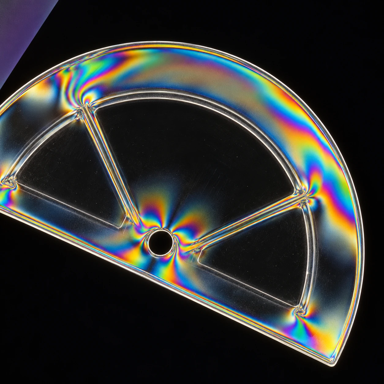
Crossed Filters Can Reveal a Clear Plastic Object’s Hidden History

A transparent plastic shape looks plain against a white screen. Hold a polarizing filter in front of it and rotate. Dark regions and colored bands appear near edges, holes, or molded features. The plastic has not filled with pigment. The setup has made differences in its interaction with light visible.

Rainbow fringes appear around the edges and hole of a clear plastic shape between dark filters.
An interpretive polarized-light view. Fringes depend on material, thickness, orientation, and stress; they are not a calibrated force map.

This is a rewarding close-looking experiment because an everyday object can carry an optical record of how it was formed or loaded. The color is striking, but the useful question is not simply where the rainbow appears. Ask what happens when the object and the filter move independently.

First establish what the filters do alone

Edmund Optics' introduction explains linear polarization and the use of crossed polarizers for examining stress-related optical changes. Two ideal linear polarizers transmit differently as their axes rotate relative to one another. A crossed pair strongly suppresses the transmitted light in the absence of a modifying sample.

If you have two suitable linear filters, rotate one in front of the other against a diffuse white light source. Never use the sun or a laser. Notice the bright and dark orientations before inserting anything. Some screens already emit substantially polarized light; a single filter in front of such a display may provide the second element of a useful setup.

Rotate a light-path model

Silent ideal polarizer and monochromatic-retarder calculator; visible equations, relative intensity and independent controls.

Open rotate a light-path model in its own window.

The silent model separates an ideal two-filter calculation from a simple birefringent-sample calculation. It uses one wavelength rather than producing a decorative rainbow. By removing color, it makes the changing brightness easier to connect with a stated relationship.

Why an apparently clear material can change the result

Nikon's MicroscopyU explanation describes birefringence: different polarization components can experience different refractive indices. Their relative phase changes while passing through the material. A following analyzer converts that phase-and-direction relationship into differences in transmitted intensity.

The optical path difference depends on both refractive-index difference and thickness. Under white light, different wavelengths can therefore produce different transmitted intensities, creating colors. Stress or molecular orientation can generate birefringence in some otherwise optically isotropic materials, including certain plastic objects.

The distinction matters. The first filter organizes the incoming polarization; the sample modifies the relationship between components; the analyzer makes part of that change visible. Calling the plastic a colored filter misses the mechanism and makes it harder to predict what rotation will do.

Rotate the sample, then rotate the analyzer

Use an ordinary clear plastic item with no sharp edges, such as intact packaging or a spoon. Place it between the polarization elements. Hold the filters still and rotate the object. Next hold the object still and rotate the analyzer. Compare which patterns move with the object and which brightness changes follow the filter orientation.

The Simon Fraser University demonstration uses plastic objects between crossed polarizers to reveal stress-induced color variations. Its setup supplies a clear physical counterpart to the idea. Different household plastics may produce different results or little visible effect; transparency alone does not guarantee a dramatic pattern.

Keep a small notebook with three observations: the unfiltered appearance, the crossed-filter appearance, and the effect of rotation. Do not bend a brittle item until it cracks. Existing molded patterns can already provide plenty to inspect without adding force.

A rainbow needs a calibration before it becomes a measurement

The generated illustration suggests a possible fringe pattern around a plastic feature. It is not a measured stress map. In a real object, thickness, material properties, orientation, wavelength, and stress state can all affect the result. A bright red patch is not a universal label for a particular force.

The model demonstrates this ambiguity without pretending to reconstruct a real object. With its crossed-analyzer sample mode, change the sample-axis angle while keeping retardation constant. Brightness changes. Then keep the angle fixed and change retardation. A similar brightness may occur at more than one setting.

Two useful model checkpoints

In the no-sample mode, ideal transmission after the first filter is 100 percent at parallel axes and zero at 90 degrees. In the crossed-analyzer sample mode, zero retardation stays dark, while a 45-degree sample axis and half-wave retardation give maximum transmission. These are ideal calculations, not measured efficiencies of household filters.

Try 45 degrees in the bare-filter model: the ideal transmitted intensity is 50 percent. Then turn to 135 degrees; the value is the same. A brightness observation alone cannot tell those orientations apart. That simple duplication is a useful preview of why a richer material pattern needs more information before it becomes a unique measurement.

The pleasure is in watching a familiar object acquire another layer of legibility. Its transparency hid variation from an ordinary glance; a carefully arranged light path makes some of that variation available. Rotate slowly, change one thing at a time, and let the pattern become a question about the material's history.

Sources and further exploration: Edmund Optics: polarization and stress evaluation; Nikon MicroscopyU: principles of birefringence; Simon Fraser University: stress plastic demonstration.

Explore all 50 new articles · Browse the complete illustrated collection

Explore more art, ideas, and independent projects at Incoprea.

The Edge of an Ink Line Reveals the Paper Beneath It

A pen draws one line across two sheets. On the first, the edge stays crisp. On the second, tiny dark branches follow the fibers outward. The pen and ink may be identical. The paper has helped decide the line's shape.

A dip pen rests beside two paper samples with crisp and feathered ink marks.
A small change in how a sheet receives liquid can change the edge of a line. These marks illustrate the comparison.

Paper sizing is easy to overlook because it does not necessarily announce itself as a visible coating. Its job concerns the relationship between liquid and sheet. A surface that looks equally white and smooth can respond very differently when a wet mark arrives.

Sizing is not the size of the sheet

In papermaker Timothy Barrett's discussion, sizing changes resistance to liquid penetration. Surface sizing is applied after a sheet forms, while internal sizing enters during manufacture. Historical and contemporary practice includes different materials and methods, so the word names a function rather than one universal substance.

Think of an ink line as both a mark and a small transport event. Liquid meets a network of fibers, pores, and treated surfaces. The final edge records where colorant ended up, while its drying behavior depends on what happens to the liquid vehicle. A crisp edge does not mean nothing entered the sheet.

The National Park Service's paper-care guidance identifies gelatin sizing as a historical way to control watery ink absorption and bleeding. The historical example explains why the treatment mattered to writers; it does not imply that every modern paper uses gelatin.

Watch three different outcomes

Feathering is the spreading of a line's edge along the sheet. Show-through concerns what is visible from the reverse. A mark can remain sharply bounded on the front while still being visible from the back because the paper is thin or translucent. Bleed-through, where ink penetrates to the reverse, is another observation again.

Drying time adds a separate dimension. A mark that stays near a surface may remain vulnerable to smearing longer under a particular ink-and-paper combination. A quick-drying line may owe something to absorption. You cannot rank all these properties with one word such as good paper.

Compare how three papers receive ink

Printable observation form separates line edge, reverse appearance and timed smear behavior.

Open compare how three papers receive ink in its own window.

The observation sheet lets you compare three ordinary paper samples. It records the pen, ink, front edge, reverse appearance, and a timed smear observation. Use scraps you own, protect the surface underneath, and keep valuable artwork or documents out of the experiment.

Make the comparison fair enough to be useful

Use the same pen and a similar stroke on each sample. Label the sample away from the test area. Keep the writing pressure modest and repeat once, since a single stroke may contain more ink or pause longer than another. If you test a smear, choose a fresh adjacent stroke for each waiting time rather than repeatedly rubbing one line.

Do not try to identify the exact sizing chemistry from the result. Fiber composition, thickness, surface texture, compression, and the ink formulation can also matter. A small comparison can tell you which sheet suits your present drawing task without pretending to be a complete materials analysis.

A useful treatment can have a complicated history

In Barrett and Mosier's research on gelatin and paper permanence, the authors examine relationships among gelatin, historic paper, and long-term properties. That conservation context keeps us from assuming that anything added to paper is automatically beneficial, or that a treatment's immediate writing performance settles its future condition.

For an artist choosing a new sketchbook, today’s line quality may be the practical question. For a conservator considering an old manuscript, existing inks, damage, treatment history, and future stability create a much more demanding decision. A kitchen-table comparison does not substitute for that work.

Choose a sheet for a particular intention

If your aim is a sharp small letter, attend to the edge. If you want a spreading wash, some liquid movement may be useful. If you will draw on both sides, inspect the reverse after drying. Write the purpose beside the result. This prevents one paper's strength in one task from becoming a claim that it is best for every use.

For a second pass, turn a fully dried sample under low-angle light. A raised or glossy trace may reveal something different from the feathered edge seen head-on. Keep those observations separate. Surface appearance and penetration are related to the same mark, but one viewpoint does not automatically report everything the liquid did.

Return to the branched edge. It is not just an imperfection to erase. It is a small visible record of an interaction that usually stays hidden. The writer moves the pen, the ink supplies the liquid, and the sheet supplies a structure with its own preferences. A line becomes more understandable when all three are allowed into the explanation.

Sources and further exploration: Timothy Barrett: sizing terminology and practice; National Park Service: curatorial care of paper; Barrett and Mosier: gelatin in paper permanence.

Explore all 50 new articles · Browse the complete illustrated collection

Explore more art, ideas, and independent projects at Incoprea.

Famous Last Meals is now in paperback — stories, history and 25 recipes

Famous Last Meals: Stories, History, and Recipes is now available in paperback on Amazon. The illustrated collection brings together 23 his...