A transparent plastic shape looks plain against a white screen. Hold a polarizing filter in front of it and rotate. Dark regions and colored bands appear near edges, holes, or molded features. The plastic has not filled with pigment. The setup has made differences in its interaction with light visible.
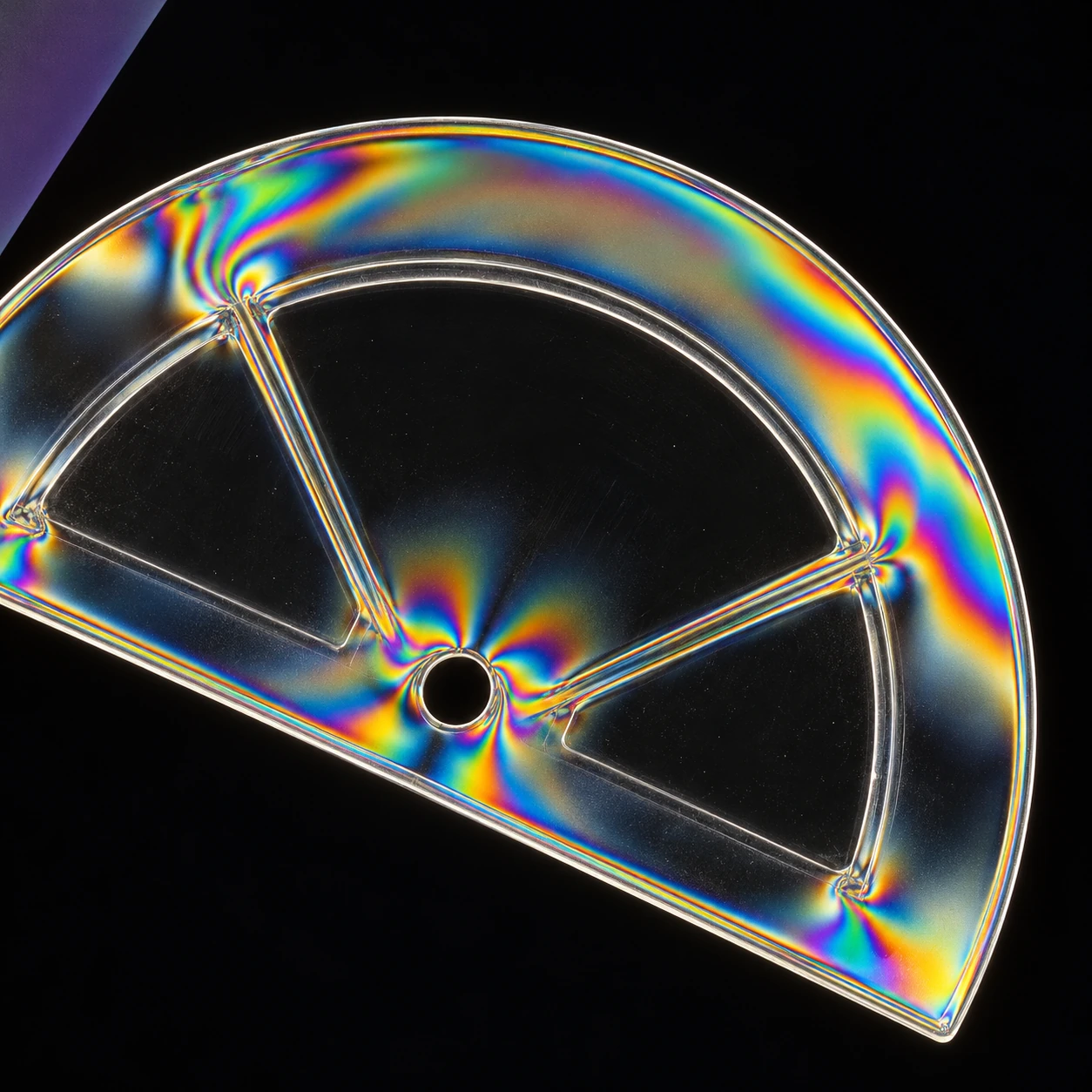
This is a rewarding close-looking experiment because an everyday object can carry an optical record of how it was formed or loaded. The color is striking, but the useful question is not simply where the rainbow appears. Ask what happens when the object and the filter move independently.
First establish what the filters do alone
Edmund Optics' introduction explains linear polarization and the use of crossed polarizers for examining stress-related optical changes. Two ideal linear polarizers transmit differently as their axes rotate relative to one another. A crossed pair strongly suppresses the transmitted light in the absence of a modifying sample.
If you have two suitable linear filters, rotate one in front of the other against a diffuse white light source. Never use the sun or a laser. Notice the bright and dark orientations before inserting anything. Some screens already emit substantially polarized light; a single filter in front of such a display may provide the second element of a useful setup.
Rotate a light-path model
Silent ideal polarizer and monochromatic-retarder calculator; visible equations, relative intensity and independent controls.
The silent model separates an ideal two-filter calculation from a simple birefringent-sample calculation. It uses one wavelength rather than producing a decorative rainbow. By removing color, it makes the changing brightness easier to connect with a stated relationship.
Why an apparently clear material can change the result
Nikon's MicroscopyU explanation describes birefringence: different polarization components can experience different refractive indices. Their relative phase changes while passing through the material. A following analyzer converts that phase-and-direction relationship into differences in transmitted intensity.
The optical path difference depends on both refractive-index difference and thickness. Under white light, different wavelengths can therefore produce different transmitted intensities, creating colors. Stress or molecular orientation can generate birefringence in some otherwise optically isotropic materials, including certain plastic objects.
The distinction matters. The first filter organizes the incoming polarization; the sample modifies the relationship between components; the analyzer makes part of that change visible. Calling the plastic a colored filter misses the mechanism and makes it harder to predict what rotation will do.
Rotate the sample, then rotate the analyzer
Use an ordinary clear plastic item with no sharp edges, such as intact packaging or a spoon. Place it between the polarization elements. Hold the filters still and rotate the object. Next hold the object still and rotate the analyzer. Compare which patterns move with the object and which brightness changes follow the filter orientation.
The Simon Fraser University demonstration uses plastic objects between crossed polarizers to reveal stress-induced color variations. Its setup supplies a clear physical counterpart to the idea. Different household plastics may produce different results or little visible effect; transparency alone does not guarantee a dramatic pattern.
Keep a small notebook with three observations: the unfiltered appearance, the crossed-filter appearance, and the effect of rotation. Do not bend a brittle item until it cracks. Existing molded patterns can already provide plenty to inspect without adding force.
A rainbow needs a calibration before it becomes a measurement
The generated illustration suggests a possible fringe pattern around a plastic feature. It is not a measured stress map. In a real object, thickness, material properties, orientation, wavelength, and stress state can all affect the result. A bright red patch is not a universal label for a particular force.
The model demonstrates this ambiguity without pretending to reconstruct a real object. With its crossed-analyzer sample mode, change the sample-axis angle while keeping retardation constant. Brightness changes. Then keep the angle fixed and change retardation. A similar brightness may occur at more than one setting.
Two useful model checkpoints
In the no-sample mode, ideal transmission after the first filter is 100 percent at parallel axes and zero at 90 degrees. In the crossed-analyzer sample mode, zero retardation stays dark, while a 45-degree sample axis and half-wave retardation give maximum transmission. These are ideal calculations, not measured efficiencies of household filters.
Try 45 degrees in the bare-filter model: the ideal transmitted intensity is 50 percent. Then turn to 135 degrees; the value is the same. A brightness observation alone cannot tell those orientations apart. That simple duplication is a useful preview of why a richer material pattern needs more information before it becomes a unique measurement.
The pleasure is in watching a familiar object acquire another layer of legibility. Its transparency hid variation from an ordinary glance; a carefully arranged light path makes some of that variation available. Rotate slowly, change one thing at a time, and let the pattern become a question about the material's history.
Sources and further exploration: Edmund Optics: polarization and stress evaluation; Nikon MicroscopyU: principles of birefringence; Simon Fraser University: stress plastic demonstration.
Explore all 50 new articles · Browse the complete illustrated collection
Explore more art, ideas, and independent projects at Incoprea.


