Showing posts with label Optics. Show all posts

Sunday, October 25, 2026

Sugar Can Turn the Plane of Light

A glass of sugar water can look optically unremarkable. It may be clear, colorless, and free of visible particles. Yet it can change light in a way that a pair of polarizing filters reveals. The effect does not require the beam to bend sideways. Instead, the orientation of linearly polarized light rotates as it passes through the solution.

A clear sample vial between two polarizing filters in a conceptual laboratory still life.
A clear sample and two polarizing filters introduce the idea of optical rotation.

What is being rotated?

Light is an electromagnetic wave. In linearly polarized light, the electric field oscillates along a defined direction perpendicular to the beam's travel. A polarizer selects an orientation. A second polarizer, called an analyzer in this arrangement, helps detect changes to that orientation. Turn the analyzer and the transmitted brightness changes. Insert an optically active sample, and the analyzer angle associated with a given brightness can shift.

IUPAC defines optical activity in terms of rotation of the plane of polarization of transmitted light. Its sign convention is also specific: clockwise rotation is positive when viewed facing the incoming beam. Clockwise without a stated viewing direction is ambiguous. The sugar molecules do not need to spin together like little paddles. Their arrangement interacts differently with the light's two circular-polarization components, allowing the combined linear orientation to rotate.

A molecule's handedness is not a plus sign

Many molecules have forms related like a left and right hand: mirror images that cannot be superimposed. These are enantiomers. Under corresponding conditions, a pair of pure enantiomers has equal and opposite optical rotation. An equal mixture can cancel the net rotation. That makes optical behavior a useful way to investigate composition, but only when the relevant substances and conditions are understood.

Several naming systems must stay separate. R and S describe configuration using structural priority rules. D and L describe a different structural relationship used for compounds such as sugars. The symbols plus and minus describe a measured optical rotation. R does not universally mean positive, nor does D universally mean positive. The IUPAC stereochemical terminology treats configuration and a racemate as distinct concepts. A zero reading is not proof that a sample contains no chiral molecules.

From an angle to a concentration

For a defined substance and suitable conditions, the measured angle depends on how much of that substance the beam encounters. A longer path through the solution produces more rotation. A higher concentration generally produces more rotation within a specified working range. Specific rotation expresses the result with concentration and path length accounted for, while recording temperature and wavelength. The concentration units must be stated because common formulas use different conventions.

A JASCO application experiment used 5 grams of sucrose per 100 milliliters of solution in a 100-millimeter cell at 20 degrees Celsius, with sodium D-line light near 589 nanometers. It reported an average measured rotation of +3.3264 degrees across five measurements. The resulting specific rotation was +66.5280 in the convention using decimeters and grams per 100 milliliters. These are the experiment's reported conditions and results, not a universal angle for every glass of sugar water.

The arithmetic is useful. In that convention, specific rotation equals 100 times the measured angle divided by concentration and path length. Here the path is one decimeter, so 100 × 3.3264 ÷ 5 gives 66.528. Doubling the path would approximately double the angle if other relevant conditions stayed fixed. Changing the light's wavelength is a different change: the specific rotation itself can change. An angle without its measurement conditions is incomplete information.

Why laboratories need unusually well-known sugar

NIST produces a sucrose reference material for calibrating polarimetric systems. Its 2022 certification report for SRM 17g documents chemical purity assessment, optical measurements, and uncertainty calculations. It assigns optical properties at specified wavelengths and conditions. That detailed work turns ordinary-looking crystals into a measurement reference. The value lies in the evidence about the material, not in a special flavor or a visually obvious difference.

A calibration asks whether an instrument gives an appropriate result for a well-characterized reference. It is different from assuming every unknown sample is pure sucrose. A mixture may contain several optically active substances, whose contributions can add or oppose one another. Cloudiness, color, bubbles, temperature errors, and incorrect concentration preparation can complicate the measurement. One measured angle cannot generally reveal every ingredient of a drink.

NIST's account of its reference materials explains why sugar producers use such standards for quality control and consistency. The broader lesson applies to many instruments: a familiar material can support demanding measurement only after someone has established its identity, value, and uncertainty. An attractive demonstration and a defensible analysis have different requirements.

Separate the demonstration from the measurement

A safe first observation needs no chemical preparation. Hold a polarizing sunglass lens in front of a white LCD screen and rotate it. Many screens become much darker at one orientation because the screen's light is polarized. A second polarizing filter provides another way to compare orientations. Different displays behave differently, and the exercise demonstrates polarization rather than measuring sugar.

The sugar experiment adds a sample, a defined path, controlled illumination, and an angle measurement to that basic idea. It shows how a transparent solution can contain information that ordinary brightness and color do not reveal. The information becomes useful when the conditions travel with the number. A small rotation can be a powerful measurement, provided we are precise about what turned, how we looked, and what was in the beam.

Sources and further reading

Continue exploring: Mantis Shrimp Vision: Light Has More Than Color; Two Matching Colors Can Stop Matching When the Light Changes.

Explore more at Incoprea.

The Reflector That Sends Light Back Toward Its Source

A roadside sign can look quietly ordinary during the day and suddenly blaze under headlights. It has not necessarily switched on a lamp. Its surface is sending a useful share of incoming light back toward the place it came from. A bicycle reflector performs the same broad trick. The effect is called retroreflection, and it differs from both a mirror's glare and white paper's scattered glow.

A bicycle reflector and roadside sign, with conceptual insets of prismatic and glass-bead structures.
Reflective signs and bicycle fittings use tiny structures to return light toward its source.

Three different destinations for the light

A flat mirror reflects light in a direction set by its orientation: the angle of reflection matches the angle of incidence. Tilt the mirror and its bright reflection moves. A matte surface sends light into many directions, allowing observers at different positions to see it. A retroreflector concentrates returned light near the incoming direction over a useful range of orientations. That makes it especially effective when the observer is close to the light source.

The Federal Highway Administration explains that sign sheeting commonly uses tiny glass beads or cube-corner structures. Both send light back toward its source, though their performance differs. “Reflective” is therefore a broad everyday word. Knowing that a surface reflects light does not yet tell us where the reflected light goes.

A corner performs three reversals

Consider three reflecting surfaces meeting like the inside corner of a cube. Each reflection reverses one component of the light's travel direction. After encounters with the three mutually perpendicular faces, all three components have reversed. The outgoing ray travels back along a direction nearly opposite the incoming one. The FHWA roadway delineation handbook describes this component-by-component reversal for cube-corner markers.

Real optical corner cubes may be solid prisms using total internal reflection, rather than three separate little metallic mirrors. Their entrance openings, material, face angles, and surrounding medium affect which rays can complete the required route. A corner cube is not equally effective from every imaginable orientation. If light cannot enter the proper faces or follow the intended reflections, the convenient geometric description no longer delivers the promised return.

Glass-bead systems achieve a similar destination by a different path. A bead acts as a tiny lens. It bends light toward a reflective region behind it, and the returning light is bent again as it leaves. The detailed result depends on the bead's optical properties, its embedding, and the reflective backing or surrounding marking material. A Texas Transportation Institute report explains the spherical-lens and prismatic approaches. A handful of ordinary glass marbles is not automatically equivalent to engineered sign sheeting.

Why the driver's eyes matter

The returned light forms a distribution around the source direction, not an infinitely thin line. A driver's eyes are separated from the headlights. The angle between the incoming headlight direction and the direction to the observer is called the observation angle. A surface that sent every photon exactly into the lamp might be less useful to the driver. Practical materials must provide suitable return toward the nearby eyes as well.

The FHWA workshop account of viewing geometry distinguishes the entrance angle. It describes how the incoming illumination meets the reflector relative to the surface's reference axis. Turn the sign or move the car and both the illumination and viewing geometry can change. Consequently, “how bright is this reflector?” is incomplete without conditions. A material measured under one geometry need not produce the same value under another. Nor does a high return coefficient guarantee readability through fog, dirt, or a poor windshield.

A useful thought experiment is to imagine two people looking at the same bicycle reflector. One holds a flashlight beside their face. The other stands well to the side. The first person may see a much brighter return because their eyes are near the source. They are not necessarily looking at different paint or experiencing a change in the reflector. Their positions select different parts of its returning light pattern.

The same family of geometry reaches the Moon

Retroreflectors also give surveyors and spacecraft a target with a known location. NASA Goddard's miniature lunar arrays use eight corner-cube prisms arranged on a small dome. NASA lists an acceptance angle of 17 degrees for each prism. The domed arrangement allows multiple directions of useful access. That specified angle is a property of those prisms, not a universal limit for all retroreflectors.

Timing a returned light pulse can support a distance measurement. The reflector itself does not need to broadcast a radio reply or generate its own flash. It supplies a passive optical destination. However, the ranging system still needs an appropriate source, receiver, pointing, timing, and treatment of the measurement uncertainties. A simple optical principle sits inside a demanding experiment. The familiar nighttime reflector and the lunar target share a geometric strategy, not identical performance.

A tabletop comparison

In a dim room, place a clean bicycle reflector beside white paper. Use an ordinary flashlight from a comfortable distance, first near your eye level and then farther to the side while you keep looking from the original position. Keep the beam away from faces and do not use a laser. Notice which surface changes brightness most strongly. The comparison is qualitative; it does not certify a safety product or measure its road performance. It does reveal that the destination of reflected light can matter as much as the amount of light a surface receives.

Sources and further reading

Continue exploring: Gold Leaf: How a Small Piece of Metal Becomes a Field of Light; Why a Camera Can Turn One Small Light Into a Star.

Explore more at Incoprea.

Saturday, October 24, 2026

Crossed Filters Can Reveal a Clear Plastic Object’s Hidden History

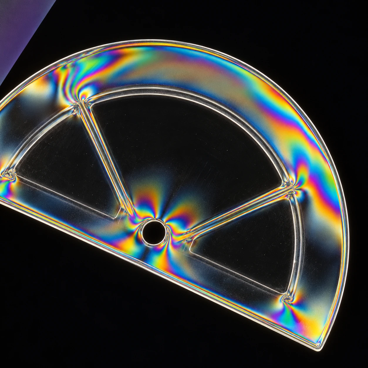
A transparent plastic shape looks plain against a white screen. Hold a polarizing filter in front of it and rotate. Dark regions and colored bands appear near edges, holes, or molded features. The plastic has not filled with pigment. The setup has made differences in its interaction with light visible.

Rainbow fringes appear around the edges and hole of a clear plastic shape between dark filters.
An interpretive polarized-light view. Fringes depend on material, thickness, orientation, and stress; they are not a calibrated force map.

This is a rewarding close-looking experiment because an everyday object can carry an optical record of how it was formed or loaded. The color is striking, but the useful question is not simply where the rainbow appears. Ask what happens when the object and the filter move independently.

First establish what the filters do alone

Edmund Optics' introduction explains linear polarization and the use of crossed polarizers for examining stress-related optical changes. Two ideal linear polarizers transmit differently as their axes rotate relative to one another. A crossed pair strongly suppresses the transmitted light in the absence of a modifying sample.

If you have two suitable linear filters, rotate one in front of the other against a diffuse white light source. Never use the sun or a laser. Notice the bright and dark orientations before inserting anything. Some screens already emit substantially polarized light; a single filter in front of such a display may provide the second element of a useful setup.

Rotate a light-path model

Silent ideal polarizer and monochromatic-retarder calculator; visible equations, relative intensity and independent controls.

Open rotate a light-path model in its own window.

The silent model separates an ideal two-filter calculation from a simple birefringent-sample calculation. It uses one wavelength rather than producing a decorative rainbow. By removing color, it makes the changing brightness easier to connect with a stated relationship.

Why an apparently clear material can change the result

Nikon's MicroscopyU explanation describes birefringence: different polarization components can experience different refractive indices. Their relative phase changes while passing through the material. A following analyzer converts that phase-and-direction relationship into differences in transmitted intensity.

The optical path difference depends on both refractive-index difference and thickness. Under white light, different wavelengths can therefore produce different transmitted intensities, creating colors. Stress or molecular orientation can generate birefringence in some otherwise optically isotropic materials, including certain plastic objects.

The distinction matters. The first filter organizes the incoming polarization; the sample modifies the relationship between components; the analyzer makes part of that change visible. Calling the plastic a colored filter misses the mechanism and makes it harder to predict what rotation will do.

Rotate the sample, then rotate the analyzer

Use an ordinary clear plastic item with no sharp edges, such as intact packaging or a spoon. Place it between the polarization elements. Hold the filters still and rotate the object. Next hold the object still and rotate the analyzer. Compare which patterns move with the object and which brightness changes follow the filter orientation.

The Simon Fraser University demonstration uses plastic objects between crossed polarizers to reveal stress-induced color variations. Its setup supplies a clear physical counterpart to the idea. Different household plastics may produce different results or little visible effect; transparency alone does not guarantee a dramatic pattern.

Keep a small notebook with three observations: the unfiltered appearance, the crossed-filter appearance, and the effect of rotation. Do not bend a brittle item until it cracks. Existing molded patterns can already provide plenty to inspect without adding force.

A rainbow needs a calibration before it becomes a measurement

The generated illustration suggests a possible fringe pattern around a plastic feature. It is not a measured stress map. In a real object, thickness, material properties, orientation, wavelength, and stress state can all affect the result. A bright red patch is not a universal label for a particular force.

The model demonstrates this ambiguity without pretending to reconstruct a real object. With its crossed-analyzer sample mode, change the sample-axis angle while keeping retardation constant. Brightness changes. Then keep the angle fixed and change retardation. A similar brightness may occur at more than one setting.

Two useful model checkpoints

In the no-sample mode, ideal transmission after the first filter is 100 percent at parallel axes and zero at 90 degrees. In the crossed-analyzer sample mode, zero retardation stays dark, while a 45-degree sample axis and half-wave retardation give maximum transmission. These are ideal calculations, not measured efficiencies of household filters.

Try 45 degrees in the bare-filter model: the ideal transmitted intensity is 50 percent. Then turn to 135 degrees; the value is the same. A brightness observation alone cannot tell those orientations apart. That simple duplication is a useful preview of why a richer material pattern needs more information before it becomes a unique measurement.

The pleasure is in watching a familiar object acquire another layer of legibility. Its transparency hid variation from an ordinary glance; a carefully arranged light path makes some of that variation available. Rotate slowly, change one thing at a time, and let the pattern become a question about the material's history.

Sources and further exploration: Edmund Optics: polarization and stress evaluation; Nikon MicroscopyU: principles of birefringence; Simon Fraser University: stress plastic demonstration.

Explore all 50 new articles · Browse the complete illustrated collection

Explore more art, ideas, and independent projects at Incoprea.

Friday, October 23, 2026

Let the Garden Enter the Dark Room Upside Down

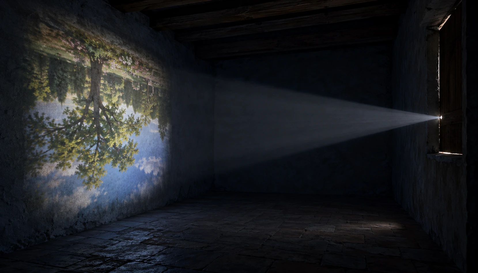
Close the shutters on a bright garden and leave a small opening. On a suitable surface inside the darkened room, a faint picture can appear. The branches point downward. The sky arrives below them. Nothing outside has turned over; the route taken by the light has organized the scene differently.

An inverted tree and sky are projected on the wall of a dark room opposite a small aperture.
The top of the outside scene reaches the lower part of the image. The room makes that crossing visible. Interpretive scene.

A camera obscura is a place to watch an image happen. It can be a room, a tent or a small box. The essential pleasure is the same: a scene appears on a surface without anybody drawing its outline.

Follow the top of the tree

The National Gallery's explanation describes light from an outside subject passing through an opening and lens into a darkened enclosure. A simple pinhole version can form an image without a lens. In both cases, we can learn something by following light from individual parts of the scene.

Imagine a straight line from the top of the tree through the small opening. Continue it until it reaches the opposite wall. It arrives below the opening. A line from the tree's base arrives above. Those crossing routes explain the inversion more clearly than saying the camera has somehow flipped the world.

Use the geometric model to move the screen without moving the object. Its colored points stand for just two locations in a scene. No actual tree or photograph is being simulated.

Follow two rays through the opening

Change object and screen distances in an ideal geometric projection with visible assumptions.

Open follow two rays through the opening in its own window.

Increase the screen distance. The separation between the projected points grows. Now hold that distance fixed and move the object farther away. The projected separation shrinks. The displayed ratio comes from similar triangles, with the opening treated as an ideal point.

Why a bigger opening is not simply better

A dark image tempts you to enlarge the hole. That admits more light, but it also lets light from one point in the scene reach a wider patch of the screen. Nearby patches can overlap. Brightness and geometric sharpness pull in different directions.

Making the hole extremely small brings another effect into importance: diffraction. The simple straight-ray model does not include it. That is why its neat lines should not be read as advice that the smallest imaginable physical opening must produce the sharpest possible image.

The Exploratorium's Cracks in a Door exhibit account began with an observation of light forming an image of an exterior column through a narrow gap. It is a reminder that an optical instrument can begin as something noticed in an ordinary building.

A box changes the work of drawing

A camera obscura in the Science Museum Group collection, made before 1753, used a lens and a mirror set at 45 degrees to project onto ground glass on top of a box. Paper could be placed there to copy the image. The instrument made the view available in a practical position for drawing.

That detail opens a useful distinction. A pinhole room shows the core projection effect. A lens-and-mirror drawing box adds decisions about brightness, focus, orientation and the artist's working posture. “Camera obscura” can therefore name related instruments whose user experiences differ considerably.

Look at the collection photographs and locate the viewing screen. Imagine trying to trace an image on a vertical wall, then on a horizontal glass surface. The optics matter, but so does where your hand can comfortably move.

A quiet indoor investigation

You do not need to black out a whole room to explore the idea. A commercially made pinhole viewer or a small enclosed demonstration with a translucent screen can make the relationship visible. Observe an ordinary bright scene, and keep the Sun out of the experiment. Never look at the Sun through a hole, lens or improvised optical device.

Before changing anything, predict which side of the screen will receive a bright object near the top of the view. Then compare the result. A prediction is more revealing than simply saying the picture looks strange after you see it.

What counts as a successful observation?

You may get a dim, soft image rather than a crisp picture. Record which shapes you can distinguish, the orientation and what happens when the screen position changes. That is useful evidence about your setup. A disappointing photograph of the projection does not mean your eyes saw nothing.

A camera obscura rewards patience because it turns a room into an explanation. Light from many parts of the garden has always been available. Restrict its routes, darken the competing background and give it a surface, and the garden arrives again—faint, inverted and unexpectedly intimate.

Sources and further exploration: National Gallery: camera obscura; Exploratorium: Cracks in a Door; Science Museum Group: camera obscura before1753.

Explore all 50 new articles · Browse the complete illustrated collection

Explore more art, ideas, and independent projects at Incoprea.

A Telegraph You Could See Only When the Weather Allowed

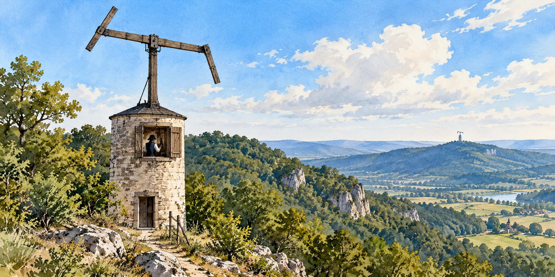
Stand below a hilltop tower and look at the sky around its mast. A large beam has moved. Two shorter arms have changed angle. To a traveler, the shape may look like a strange mechanical person. To an operator watching through a telescope at the next station, it can be a signal that needs to be copied accurately.

An optical telegraph mast rises above a hilltop tower, with another ridge beyond.
The gaps between stations belong to the technology: a visible signal needs a usable line of sight. Reconstructed scene.

The Chappe optical telegraph makes a network visible. Its stations needed a view of one another, its moving parts needed recognizable positions, and its operators needed shared rules. The message traveled as a sequence of shapes, while the physical apparatus stayed on its hill.

Do not begin by guessing letters

The Musée des Arts et Métiers' explanation describes a succession of semaphores on towers or elevated points. The mechanism's central regulator and its shorter indicators could form distinguishable configurations. The system required both a visible signal and a convention for using it.

That does not mean every position simply stood for one letter of the alphabet. Historical optical telegraphy involved codes and operating signals as well as apparatus. A clear view of the arms would not automatically reveal a message to someone without the relevant code and procedure.

Imagine you and a friend agree that an upright hand means “ready,” a sideways hand means “repeat” and two hands mean “finished.” Those are instructions about the conversation itself. They do not belong inside the sentence being sent, but the sentence becomes difficult to send reliably without them.

Build a deliberately tiny relay

The interactive exercise uses invented symbols with an invented four-item vocabulary. It is not a reconstruction of Chappe's historical code. Choose a message, pass its symbols through a relay and decide what to do when one symbol becomes uncertain.

Send a message through a visible relay

An invented four-symbol relay shows why repeat and uncertainty rules matter.

Open send a message through a visible relay in its own window.

First, relay the sequence with every symbol visible. Next, hide the middle symbol. Notice the difference between “I saw a shape that means B” and “I think B would make sense here.” A plausible guess can produce a convincing wrong message. A request to repeat may feel slower, but it makes uncertainty explicit.

The model counts your transmissions, including repeats. It does not calculate a historical dispatch time. Real towers had distances, sightlines, mechanical movement and staffing conditions that the small demonstration omits.

Weather is part of the communications channel

The museum's Chappe model record places the optical apparatus within a broader history of telegraphy. Its preserved mechanism lets us study how movement became a reproducible signal. It does not remove the basic requirement that the next station must see that signal.

Fog, terrain and darkness are not decorative background in this story. They affect whether the channel is available. A beautifully articulated arm cannot solve a hidden horizon. Raising the station, improving observation and choosing a route are therefore parts of the technology just as surely as the gears are.

Try a paper planning exercise. Put three hills between two towns. Draw one line of sight that reaches every intermediate station. Then add a ridge that blocks the middle segment. Would a taller mast solve your drawing, or would you need another station? You have created a geometry problem before sending a single word.

A photograph is not a transmission

A Paris Musées record of a Chappe monument documents a later public image of the inventor and apparatus. That is evidence for commemoration, rather than a photograph of a working message on its way between stations. Museum objects and later monuments answer different questions.

The distinction matters when browsing historical images online. An engraving might simplify the mechanism so readers can recognize it. A restoration might choose one position for display. A model might expose parts normally hidden inside a tower. Ask what the image was made to show before using it as a record of operation.

One question to take outside

Find a distant building you can see clearly. Without approaching it, list which changes you could distinguish: a large flag, an open window, a hand gesture, a written word. Visibility has a scale. Designing a signal means choosing differences that survive that scale.

Chappe's towers are memorable because the message was briefly part of the skyline. Their deeper lesson is that communication needs more than a clever symbol. It needs a usable channel, a way to acknowledge doubt and people who agree when a shape has been seen well enough to pass onward.

Sources and further exploration: Musée des Arts et Métiers: how the Chappe telegraph works; Musée des Arts et Métiers: optical telegraph model; Paris Musées: Chappe monument record.

Explore all 50 new articles · Browse the complete illustrated collection

Explore more art, ideas, and independent projects at Incoprea.

The Third Pattern Hiding Between Two Fences

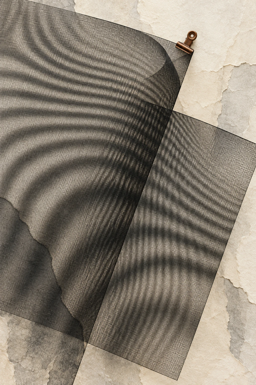
Two fences can make a third pattern that belongs to neither fence. Walk past one mesh with another behind it and large dark bands seem to travel across the view. Each wire stays where it was. The moving pattern comes from a changing relationship between repeated structures.

Two angled mesh sheets create broad dark bands on ivory paper
Overlapping meshes turn a fine structure into a much broader pattern.

This is moiré. It can make a fine striped shirt misbehave in a photograph or turn layered sheets of mesh into an unexpectedly large visual rhythm. The broad bands are easier to follow than the tiny lines that create them, which is why a very small mismatch can announce itself at a much larger scale.

Make the mismatch larger than its ingredients

Begin with two transparent sheets carrying parallel dark lines. Give one a line every ten millimeters and the other a line every eleven. Near a point where the lines align, much of the open space remains clear. Move along and the second set gradually slips relative to the first. Farther on, its lines occupy different parts of the gaps.

The local light transmission changes with that alignment. After 110 millimeters, eleven ten-millimeter intervals and ten eleven-millimeter intervals have brought the patterns back into register. The resulting repetition is much wider than either original pitch. For ideal parallel line patterns, the beat spacing is p × q ÷ |p − q|. Ten and eleven give 110.

That equation describes a simplified geometric relationship. Actual contrast depends on line thickness, opacity, illumination, and the surface being viewed. A photograph adds its own pixel grid and processing. But the simple arithmetic explains why almost matching patterns can produce surprisingly wide bands.

Layer two grids

Adjust pitch and relative angle with static grids and a numerical beat-spacing readout.

Open layer two grids in its own window.

The model keeps the two layers separate enough to inspect. Change the second pitch while leaving the first fixed, then return to equal pitches and rotate one layer slightly. If the lines are difficult to resolve on your screen, use the text readout and compare the broad bands rather than judging individual fine lines.

A rotation creates a different route to repetition

Equal pitch does not prevent moiré. Rotate one layer by a small angle and the lines cross. Their changing alignment produces a new, larger-scale arrangement. As the relative angle grows, the broad pattern changes. The display is a stationary mathematical construction controlled by you, not a flashing or automatically moving optical test.

The Marquette physics laboratory notes distinguish pitch mismatch from rotation and explain how grids attached to a specimen can reveal deformation. In the basic occluding-grid case, the bands arise geometrically. They do not require light waves to diffract through the mesh.

This distinction prevents an attractive but misleading explanation. The large pattern can look like a water-wave interference pattern. A similar mathematical idea of relative phase is useful, but visible bands made by one black grid covering another need not be a demonstration of optical wave interference.

Use the bands as a magnifying relationship

Imagine drawing a fine grid on a sheet before stretching it. Compare the stretched grid with an unchanged reference. A tiny difference in spacing can create a broader fringe pattern that is easier to count. The measurement comes from a known relationship between the reference and the altered specimen.

Try this as a paper thought experiment. If the first pitch is ten units and the second becomes 10.1, their beat spacing is 1,010 units. Make the mismatch larger, to eleven, and the beat spacing shrinks to 110. A wider fringe does not necessarily mean a larger underlying change. Close agreement can produce the widest visible beat.

This is also a good prediction challenge for the model. Before adjusting the slider, decide whether a second pitch moving closer to the reference should spread the bands apart or squeeze them together. The calculation supplies an answer even when display resolution makes a particular view imperfect.

The camera can become the second grid

A real subject does not always need a second physical mesh behind it. A digital image samples spatial detail. When the subject contains repeated structure too fine for that sampling arrangement, the recorded image can contain a larger pattern absent from the intended subject. Changing distance, angle, or image processing can change the result because the relationship between subject detail and sampling has changed.

For a photographer, the important question is where the pattern was introduced. Inspect the actual fabric, the camera’s original file, and the final resized image separately. A pattern that appears only after resizing points to a different stage from one visible in the original capture. This is a diagnostic exercise, not a promise that one adjustment fixes every camera or fabric.

The Exploratorium’s pattern table invites visitors to layer and rotate transparencies. Its companion Moiré Patterns exhibit gives the same phenomenon a physical setting. Both offer an appealing starting point because you can watch the ingredients remain simple while their combination changes dramatically.

Read a relationship, not a hidden object

The broad dark band is not an extra strip of material laid across the fences. It is a region where the repeated structures combine to transmit less light. Move your viewpoint and the relationship changes, so the apparent band can travel without any wire following it.

That is what makes moiré useful beyond its visual appeal. It teaches you to look for an interaction between systems before inventing a third object. A small mismatch, seen through repetition, can become the biggest and most noticeable feature in the scene.

Follow the evidence: Marquette physics laboratory: low-frequency moiré; Exploratorium: Moiré Patterns Table; Exploratorium: Moiré Patterns.

Explore all 80 new articles · Browse the complete illustrated collection

Explore more art, ideas, experiments, and independent projects at Incoprea.

Why a Camera Can Turn One Small Light Into a Star

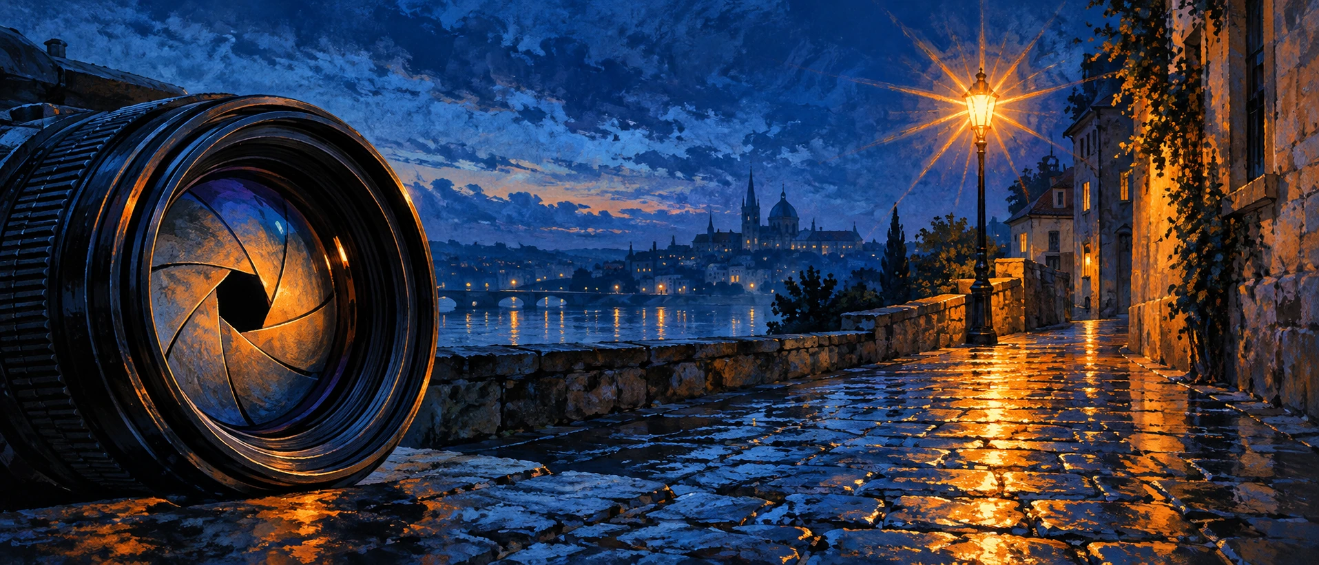
A small streetlamp looks ordinary while you stand beneath it. In a photograph it can acquire long, sharp rays, as if a tiny star has been installed above the pavement. The rays do not have to belong to the lamp. They can be a signature of the opening inside the lens.

Illustrated wet street at blue hour with a small lamp rendered as a starburst and a camera lens in the foreground.
A small bright light can reveal the aperture’s geometry. The illustration suggests the effect; it is not a measured comparison.

This makes the effect especially satisfying to investigate. The scene can stay nearly unchanged while the camera's treatment of it changes. Instead of asking whether the photograph is “what was really there,” ask which parts of the result describe the scene and which reveal the instrument that recorded it.

The opening has edges

A lens diaphragm uses overlapping blades to change the aperture: the opening through which light passes. Canon's diaphragm definition describes this mechanical iris. Open it widely and the blades leave a broad passage. Close it down and their edges shape a smaller one.

Light does not travel through that opening as an indefinitely narrow collection of perfectly independent rays. Diffraction spreads the response to a point of light. With suitable aperture geometry, the image develops recognizable spikes. Nikon's starburst guide recommends a small, bright source against darker surroundings and experimenting with smaller apertures. A distant night light provides a convenient subject without needing the Sun.

The number on the lens can run against intuition

A larger f-number means a smaller relative opening. Moving from f/4 toward f/11 closes the aperture down rather than opening it. That language matters when you compare photographs: “larger aperture” and “larger f-number” point in opposite directions.

Keep a record of what you changed. If you alter aperture, exposure time, focus, camera position, and image processing together, the comparison may look dramatic while explaining very little. A useful small experiment asks one question at a time. What changes when the opening changes and the framing remains fixed?

Count blades carefully; count rays more carefully

Canon's photographic guide describes a useful pattern: an even blade count commonly produces the same number of starburst rays, while an odd count commonly produces twice as many. Opposite parallel edges can place spikes on top of each other. An odd-sided opening lacks those same paired overlaps.

That rule describes an idealized geometry, not a guarantee that every point will be equally visible in your picture. Blade curvature, the chosen aperture, the brightness and size of the source, and the rest of the optical design affect the appearance. Counting faint rays in a processed image can be less reliable than the neat diagram in your imagination.

Predict before checking the manufacturer's example

A simplified six-bladed opening has opposite pairs of edges, so the usual count is six visible ray directions. A simplified seven-bladed opening usually gives fourteen. Now ask a different question: would a much brighter central patch help you count, or could it hide the bases of the rays? A photograph can make a theoretically simple count practically awkward.

A stronger effect is not automatically a better photograph

Closing the aperture further can make starbursts more pronounced, but diffraction also spreads image detail. Canon explicitly notes that very small apertures can soften the picture. There is a choice to make between the look of a light source and the rendering of the rest of the scene. The most interesting setting is the one that serves the picture you intend.

It is also worth separating a starburst from every other bright-light artifact. Reflections within a lens can create flare or ghost shapes. Camera movement can stretch a light into a trail. Deliberate star filters can add their own pattern. Several causes can coexist, so the presence of a ray is a starting clue rather than a complete diagnosis.

Once you notice the instrument's contribution, these night photographs become a small lesson in observation. A camera does not simply collect a finished image from the world. Its aperture helps make the image. A familiar lamp can tell you something new about a set of blades you rarely see.

Keep exploring: Nikon: adding star power; Canon: capturing sunbursts; Canon: diaphragm glossary.

Explore all 80 new articles · Browse the complete illustrated collection

Explore more art, ideas, experiments, and independent projects at Incoprea.

Thursday, October 22, 2026

The Hidden Geometry That Makes Road Signs Shine Back at You

An anonymous road sign shines in headlights beside a quiet dark road.
Night-road illustration. Apparent brightness is artistic and does not represent a measured sign performance.

At night a road sign can appear to switch itself on as a car approaches. Yet the sign may have no electricity, lamp or stored glow. Its surface is arranging a return journey: some of the light from the headlights is being sent back toward the place it came from. Because the driver's eyes are close to that place, the sign becomes conspicuous.

This is retroreflection. A shiny mirror also reflects light, but its bright reflection depends on a particular geometry. A retroreflective surface is designed to return light toward its source over a useful range of directions. The difference is not how expensive or glossy the surface looks in daylight. It is where the outgoing light goes.

Three different answers to a beam of light

Imagine aiming a flashlight at three samples: matte card, a mirror and a strip of reflective material. A matte surface spreads reflected light into many directions. A mirror sends a narrow reflection along the direction fixed by its orientation. Retroreflective material returns a substantial part of the beam toward the source. 3M's optical primer diagrams these three behaviors.

That means “reflective” is too broad a word to predict a driver's experience. A polished surface can direct light away from the observer. A surface that looks relatively unremarkable in a room can be very effective when illuminated from near the eye. The useful comparison specifies the light source and observer together.

The pattern is smaller than the message

The Federal Highway Administration's explanation identifies two common approaches: tiny glass beads and very small cube-corner structures. Both can be built into sheeting that covers a sign. A large printed instruction thus depends on an optical structure too small for a driver to inspect while reading it.

A cube corner is easiest to imagine as the meeting of three mutually perpendicular mirror faces. Reflections reverse the direction components of an incoming ray, sending it back roughly parallel to its arrival direction. That is a geometric account of an idealized element, not a claim that every ray entering a real sheet returns perfectly. Actual products have limited angles, finite efficiency and protective layers.

The engineering task is subtler than building a perfect return to one mathematical point. Headlights and eyes are separated. Light returned only to the exact filament location would not help the driver above it. Real useful reflection has an angular distribution that includes the intended observer.

The observer is part of the apparatus

The manufacturer's discussion of observation angle distinguishes the incoming headlight line from the line returning to an observer. A larger separation angle can reduce apparent brightness. This helps explain why the same sign can present different conditions to different vehicles without changing its material.

Try an original geometry estimate. Let a light and an eye be separated vertically by one meter. At a target distance of 100 meters, the small observation angle is approximately 1/100 radian, or 0.57 degrees. At 20 meters, the same separation corresponds to about 2.9 degrees. These are simplified straight-line calculations, not a sign specification. They show why distance and observer height belong in the question.

There is also an entrance angle: how the arriving beam approaches the surface compared with its perpendicular. Do not confuse that with the light-to-eye separation. One describes the sign's presentation to the beam; the other describes the observer's relationship to the source. A meaningful measurement records the geometry rather than announcing one context-free brightness number.

Rotating the sample asks a third geometric question

You can keep a lamp, sample and eye in the same places while changing the sample's orientation within its own plane. Imagine turning a square like a clock hand without tipping it toward or away from the beam. That rotation is a different adjustment from changing the entrance or observation angle.

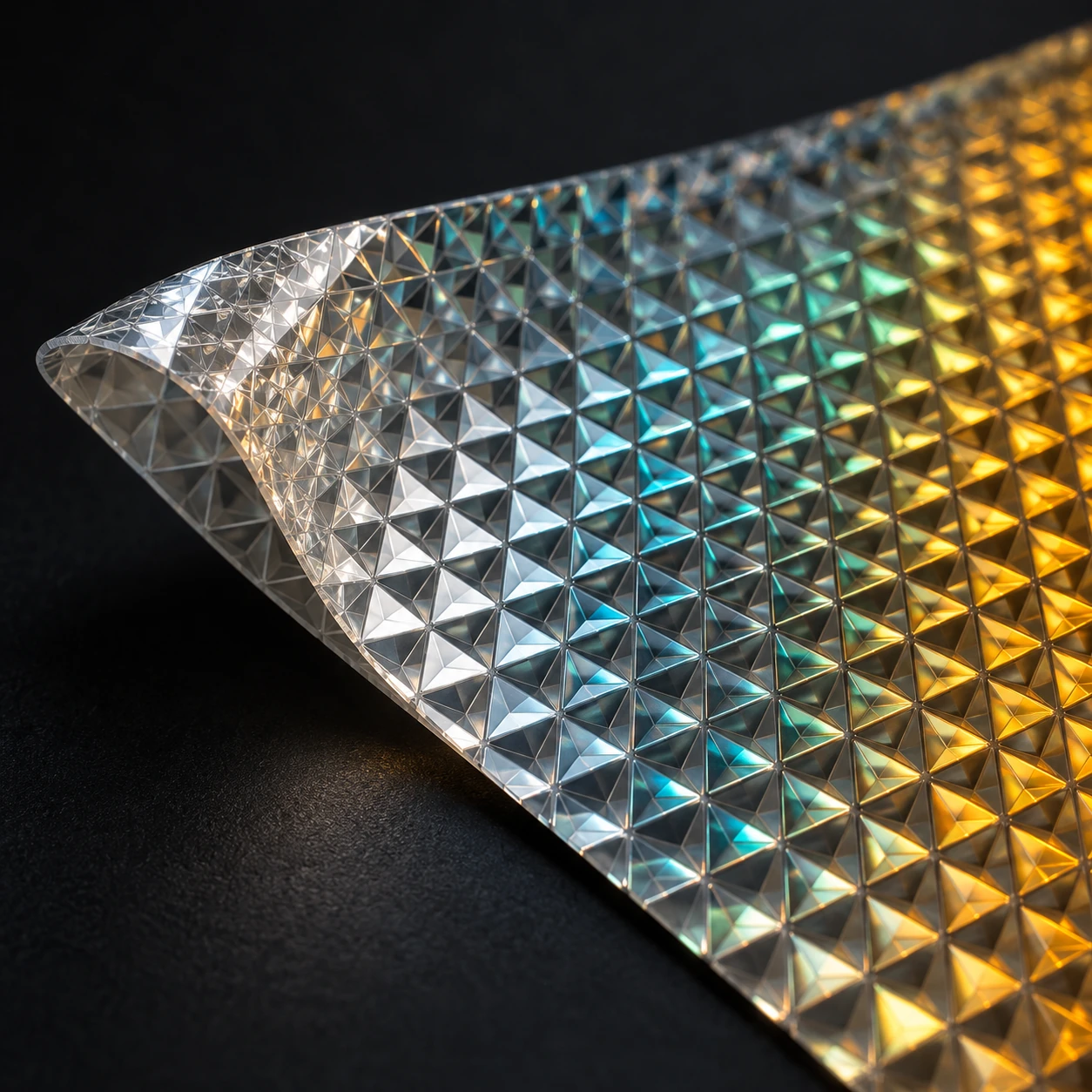
Close material study of a partly folded reflective sheet with enlarged triangular facets.
Interpretive material study. Facets are enlarged, and glints do not measure retroreflectivity or identify a specific product.

FHWA's assessment-method discussion explains that glass-bead sheeting tends to be comparatively insensitive to this rotation, while prismatic sheeting can be sensitive. An instrument that gathers light around an annulus can therefore give a different account from one that samples a particular point geometry. “Measured brightness” needs the instrument's arrangement as well as the material's name.

The agency's materials guide also separates the optical sheeting from the rigid backing that carries it. The message may look like one object, but the backing's structural role and the surface's optical role remain different jobs. A sturdy flat panel does not by itself specify where light returns.

A rotation record for a loose sample

Extend the safe indoor exercise using only a loose reflector or reflective scrap. Keep its position and tilt fixed. Rotate it within its plane through quarter turns while the flashlight and your eye stay put. Note each orientation before comparing it with the starting one again. Do not alter an installed sign or draw conclusions about road compliance.

If the brightness changes, your record documents orientation-dependent appearance under that arrangement. It does not uniquely identify the internal technology. If the brightness seems unchanged, that likewise does not prove the material contains beads: your viewing geometry and visual sensitivity may simply make a difference difficult to detect.

Write a small observation table with four fields: orientation, source position, observer position and description. A photograph can accompany the record, but its automatic exposure may compensate for the very difference you are trying to preserve.

This adds a rewarding complication to the ideal cube-corner explanation. Reversing a ray's direction in a simple diagram is the beginning of the optics. An actual sheet organizes many finite elements, and the instrument chooses which part of their returned-light pattern to count. The sign shines toward a useful neighborhood, while measurement samples that neighborhood in a particular way.

A daytime glance cannot finish the inspection

FHWA's guidance describes assessment and management of sign retroreflectivity, including measurements and nighttime inspection methods. That practical work follows from the optical difference: readable paint in daylight does not by itself establish an adequate light return at night. Material age, condition and viewing circumstances matter to the sign's actual task.

A useful analogy is a microphone tested without a listener's room. The device has measurable properties, but the final experience depends on its arrangement. For a sign, the material, headlight beam, distance, alignment and observer all participate. Improving only the apparent color on a sunny afternoon can miss the part of the system that matters after dark.

The next time a sign brightens through a windshield, the apparent little lamp is worth a second thought. The sign is borrowing light and returning it to a useful neighborhood. A message large enough to guide a vehicle depends on an immense population of tiny structures, each doing a modest piece of geometry.

Sources and a closer look: FHWA: sign retroreflectivity and materials; 3M: optical principles and viewing angles; 3M: observation angle and returned light.

Explore art, experiments and other unexpected connections at Incoprea.

Fata Morgana: The Horizon That Builds Castles From Refracted Light

Pastel illustration of a distant cold-ocean island distorted into narrow stacked and stretched bands at the horizon.
Illustrative interpretation of a complex horizon mirage, not a documented sighting. Distortion is emphasized for visibility.

A distant shoreline can rise into a row of towers, stretch into thin pillars, split into upright and inverted pieces, then collapse back into a low strip of land. The landscape has not rebuilt itself. The route taken by its light has changed.

A complex mirage commonly called Fata Morgana can give the horizon this architectural appearance. Its fascination comes partly from a mismatch: your visual system tries to interpret familiar solid objects, while the atmosphere delivers a vertically scrambled image.

Start with an actual object

A mirage is not a hallucination. Light from real scenery reaches the observer along bent paths through air with a changing refractive index. A camera can record the resulting image. What becomes unreliable is the straightforward assumption that the object lies in the direction from which the arriving ray appears to come.

Atmospheric-optics researcher Andrew Young’s introduction at San Diego State University explains how temperature-dependent refraction creates mirages. The observer traces the final direction backward as though the ray had traveled straight. When the actual path was curved, that construction assigns the object an altered apparent position.

This makes a mirage a useful distinction between reliable detection and reliable interpretation. You truly received light. Its apparent direction does not necessarily provide the undistorted geometry you expected.

Layers can rearrange a horizon

Over a cold surface, warmer air can lie above colder, denser air. Strong vertical refractive gradients can produce superior mirages and optical ducts. Complex structures allow several ray paths to connect different parts of a distant object with the observer, producing stretching, compression, inversion, and multiple images.

Young’s detailed Fata Morgana discussion emphasizes the striking vertical elongation and apparent architecture associated with the name. It also shows why a picturesque historical description is not a complete physical diagnosis. Small changes in observer height and atmospheric structure can substantially change the display.

The mirage’s narrow vertical zone matters. Popular illustrations sometimes put a fully formed castle high in the sky. Actual complex horizon mirages tend to transform distant scenery within a compressed region near the apparent horizon. A giant fantasy city is a poor model of what an observer is looking for.

The name is less tidy than the physics

The American Meteorological Society’s glossary explicitly notes that the precise circumstances under which the term should be applied are ill-defined. That is a valuable limitation to retain. Not every photograph of a seemingly hovering ship establishes a complex Fata Morgana.

A superior mirage can elevate or invert an image without producing the elaborate stacking often associated with this name. Sometimes an indistinct or false horizon contributes to a floating appearance. A single cropped image may omit exactly the context needed to distinguish those possibilities.

Being cautious with the label does not make the phenomenon less interesting. It redirects the question from “Which exotic name wins?” to “Which refractive structure and viewing geometry could produce these observed features?” That is a question a sequence of observations can help answer.

A reflected-looking image without a reflecting surface

A mirage invites the eye to invent a mirror. An inverted strip below a distant object can look as though water reflects it; an inverted strip above can suggest a second floating object. But a refracted ray need not bounce from a sharp boundary. It can bend continuously through air whose optical properties change with height.

A telescope at a grassy coastal overlook facing a distant low island
Observational scene with a subtly distorted horizon; no documented sighting is implied.

Andrew Young’s ray-tracing introduction is useful here because it follows light routes rather than merely naming the resulting shapes. Its inferior-mirage example also changes the apparent horizon. The familiar “reflection” description can help identify an inverted image, but it can mislead about the mechanism.

The Atmospheric Optics superior-mirage account supplies a contrasting observational view. Instead of memorizing “hot road below, cold sea above,” compare the object, the viewer, and the refractive structure. The naming shorthand does not replace those three parts of the geometry.

A laboratory preprint on inferior mirages provides a useful contrast: controlled temperature gradients produced upright and inverted images without requiring a sheet of reflective water. That experimental analogy addresses selected optical features, not the full structure of an outdoor Fata Morgana.

Match a landmark before naming a castle

Use two views of a recognizable coast from the same general direction: one ordinary, one apparently distorted. A public example with an identified subject is preferable to an anonymous social-media crop. On tracing paper, mark only three distinctive features in the ordinary view: perhaps a notch, a mast, and a sloping headland. Search for those features in the distorted bands without forcing the intervening silhouette to match.

If the features repeat in reversed vertical order, describe that observation. If they merely stretch, describe the stretching. Leave blank any band you cannot associate with the known scene. A blank is better than a confident tower invented from a dark edge.

Now ask what a tighter crop would remove. It might hide the ordinary image below an inverted one, conceal the waterline, or eliminate a reference that shows the feature’s tiny angular height. Context can change the diagnosis even when no pixel in the surviving crop changes.

One final comparison concerns observer height. Draw two eye positions without changing the distant land. Different rays can reach them through the same layered air, so a changed image is not necessarily evidence of a changed object. The viewing position belongs in a mirage record for the same reason camera settings belong in an exposure comparison: it changes the experiment.

The aim is not to diagnose a full atmospheric profile from a scenic picture. It is to recover the real subject from a persuasive visual impression, keeping the missing information visible while the illusion remains enjoyable.

A shoreline observation notebook

If a distant coast or ship looks distorted, stay at a safe public viewpoint and make a short sequence rather than one tightly cropped photograph. Include enough surrounding water and sky to preserve the apparent horizon. Record the time, approximate viewing height, direction, and the identity of fixed landmarks when known.

  1. Take a wide contextual image before zooming in.
  2. Photograph the same feature repeatedly as the atmosphere changes.
  3. If safely possible, compare a modestly higher or lower viewpoint.
  4. Describe what changed: inversion, duplication, vertical stretch, or disappearance.
  5. Keep “possible mirage” separate from the more specific classification.

This is an observational guide, not a way to measure the full air-temperature profile from photographs alone. Nearby weather-station data may also fail to represent the thin refractive layers along a long water path.

Why height is such a strong clue

Draw a distant lighthouse and two observers at different heights. In uniform air, the geometry changes predictably as the viewpoint rises. In layered air, each observer can sample a different collection of curved ray paths. A layer that produces multiple apparent images for one viewer may place another viewer outside the necessary geometry.

The sketch is not a ray-tracing solution. It is a way to understand why “I stood beside someone and saw a different shape” need not imply imagination. The two observers may have different optical access to the same distant object.

Roland Stull’s atmospheric-optics chapter provides the broader physical framework of refraction, optical paths, and atmospheric effects. A useful next exercise is to compare its ray diagrams with an observed sequence and identify which features the simple drawing explains and which require a more complex profile.

For a useful comparison, sketch the undistorted outline of a known island from a clear-day photograph. Beside it, draw only the features you can identify in the miraged view. Leave the uncertain connections blank. Matching a recognizable notch or headland across the distorted bands is stronger evidence than deciding that the whole shape resembles a familiar building. The comparison makes interpretation answerable to a real object.

A photograph can preserve the wrong inference

Digital zoom enlarges the distorted image; it does not remove the refractive distortion. Sharpening can make a narrow bright edge look more architectural without establishing a real tower. A caption should therefore describe both the distant subject and the optical conditions inferred from the image.

There is also a scale problem. A telescope compresses a huge horizontal distance into a small frame. Without a known object, the viewer may assign an invented size to a thin band. Keeping the uncropped frame and a familiar landmark makes the picture more useful than a dramatic isolated silhouette.

The wonder survives this discipline. An ordinary island has become an experiment in how we know where things are. The apparent castle belongs neither wholly to the landscape nor wholly to the mind: it is the product of a real object, a structured atmosphere, and a particular place to stand.

Sources and a next step

Continue exploring art, ideas, and unexpected connections at Incoprea.

Wednesday, October 14, 2026

Viking Sunstones: A Beautiful Optical Idea with an Evidence Gap

A transparent crystal that helps a sailor estimate the hidden Sun's position sounds like an object from a saga. The optical idea is real enough to test. Whether Viking navigators actually used such a procedure is a different historical question.

The proposed sunstone is most interesting at that junction. Light, crystals and human judgement can be investigated experimentally. Texts and objects can be examined for evidence of past practice. Bringing the results together is useful precisely because neither discipline can do all the work by itself.

Illustration of a clear calcite crystal doubling a dark line, with a cloudy sea and wooden vessel behind.
A visual interpretation of the optical hypothesis, not evidence of a recovered Viking tool.

The sky carries a pattern

Sunlight scattered by the atmosphere can become polarised: the light has a patterned orientation rather than every direction being represented equally. Under suitable conditions, that pattern relates to the Sun's position. A patch of sky can therefore carry information beyond its apparent brightness.

Certain crystals interact with polarisation in ways an observer can use. Transparent calcite, often called Iceland spar, is a prominent candidate in the sunstone hypothesis. Its double refraction also makes an image viewed through it appear doubled, a striking effect that is easier to recognise than the full navigation proposal.

Double refraction and a useful sky observation are connected through the crystal's optical properties, but they are not the same demonstration. Seeing a doubled word proves that a crystal changes the path of light. It does not establish that someone has located the Sun accurately.

From optical effect to navigational estimate

A proposed method has several stages. The observer must make a judgement about the light, relate that judgement to solar position and use that estimate within a navigation system. Each stage can introduce error. The interesting question is not simply whether a crystal has an effect, but how reliably a whole procedure performs.

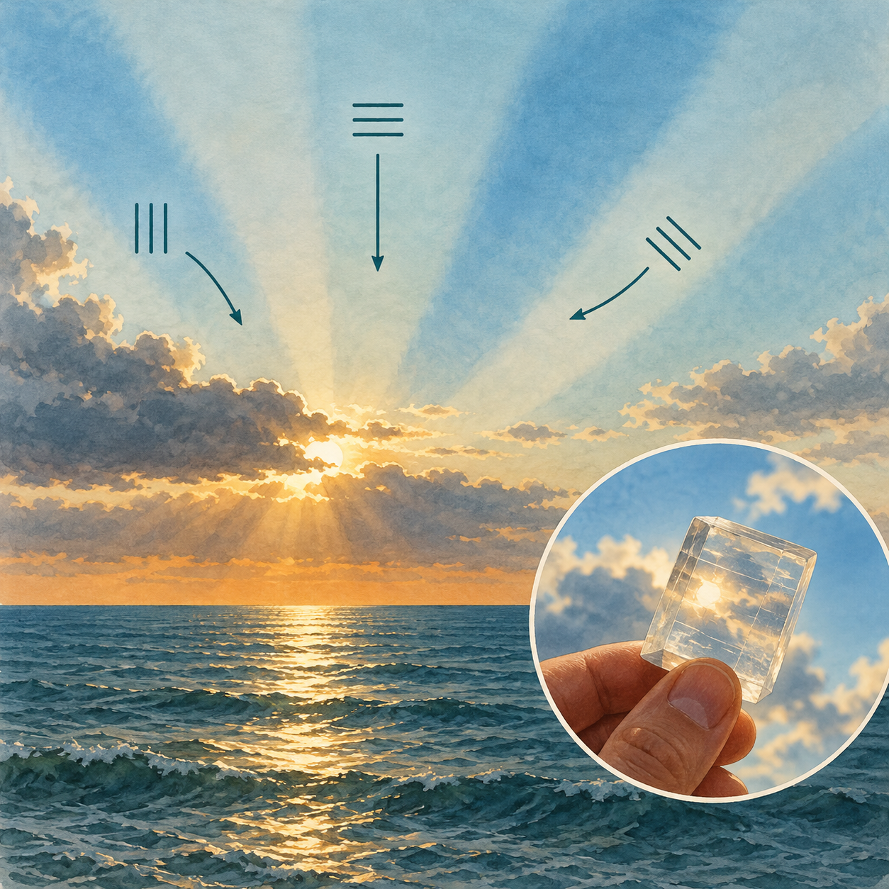
Conceptual illustration of polarized skylight and a transparent crystal.
Sky polarization is a physical effect. The symbols are conceptual and do not establish how Viking navigators worked.

The schematic sky illustration separates the general idea from a historical equipment claim. It does not show a verified Viking instrument or an observation with measured accuracy. For the experiments, turn to the published research and its stated conditions.

A 2017 study explicitly called the system hypothetical and examined accuracy under different solar elevations and sky conditions. Its authors discussed limitations when moving from experimental settings to an actual voyage. A rolling vessel, cold hands and variable visibility make a different observing platform from a controlled demonstration.

What a 2026 classroom study adds

An American Journal of Physics paper published in 2026 uses the speculative history as a context for undergraduate experiments. It combines a simplified sun compass with polarimetric sky observations. The historical uncertainty is stated in the title and abstract rather than hidden behind the activity.

Its student results found the polarisation approach most useful under partly cloudy conditions; a fully obscured sky made the signal difficult or impossible to observe in the activity. That is a useful correction to the romantic image of a crystal defeating any weather.

The result is about a particular exercise with particular observations. It should not be expanded into a claim that every proposed method has been tested under every Arctic condition. Equally, a successful exercise can teach real optics without proving a medieval practice.

A small evidence challenge

Imagine three new discoveries. First, an experiment shows that a crystal gives accurate estimates on a partly cloudy afternoon. Second, a medieval passage mentions a sunstone. Third, a crystal is found in an archaeological setting connected to seafaring. Which historical claim does each support?

The experiment supports feasibility under its tested conditions. The passage supports investigation of a term in its textual context. The find supports investigation of an object in its archaeological context. To argue for routine Viking navigation, the connections among those kinds of evidence must also be demonstrated.

Why does “could have” matter?

It marks a possibility established or explored by evidence. “Did” makes a claim about an event or practice. Replacing one with the other requires further support, not merely a more impressive modern demonstration.

Try the exercise with another technology you know. A method can be physically workable, historically available and still not have been the one used on a particular occasion. The distinction prevents experimental archaeology from being asked to prove more than its design can test.

Look at the experiment's conditions

Begin with the Royal Society introduction, then open the 2026 teaching study. Locate its account of sky conditions and compare the purpose of its classroom activity with the historical claim in the popular introduction.

For a deeper route, the 2017 paper and a later sensitivity study investigate how assumptions affect a modelled journey. Notice what is treated as an input: the frequency of observations, the date, conditions and decisions about sailing. A model's answer is conditional on its setup.

You do not need to carry out an outdoor Sun-finding exercise to appreciate the result. Comparing a figure's conditions and the authors' claims is already an active way to read the science. It also avoids mistaking a conceptual picture for an observing instruction.

The open history is part of the appeal

The sunstone does not have to become a solved Viking secret to remain compelling. It reveals a subtle structure in daylight and a clever interaction between a material and an observer. It also demonstrates how a good question can survive while its answer remains incomplete.

Keep the historical and optical questions beside one another. A crystal can do something remarkable with light. Establishing who used it, where and for what purpose asks for another kind of evidence. That combination makes the subject richer than either a dismissal or an announcement that a saga has finally been proved.

Sources and further reading

Explore more art, stories and discoveries at Incoprea.

Famous Last Meals is now in paperback — stories, history and 25 recipes

Famous Last Meals: Stories, History, and Recipes is now available in paperback on Amazon. The illustrated collection brings together 23 his...